This project is something I have had on my mind for several years
now. It all started when I saw reports of members on the 4HV forum
doing their own X-ray experiments. What's more it didn't appear to
require much skill in the electronics department, which I lacked at the
time. Some of the inspiring experiments can be seen here
and here.
Of course I thought it was absolutely amazing, but at the same time the
idea of exposing myself to radiation didn't appeal to me at all. So I
decided to NOT to conduct X-ray experiments. Well, obviously curiosity
got the better of me, and I ordered an X-ray tube from ebay a year ago.
Mind you this was three years later, so my will power isn't terrible,
and above all I had picked up some knowledge on safety. At the same
time I had purchased the core for the big-Mofo
transformer, and had
also started working on a CW
multiplier. That the two would
one day be united wasn't planned.
Construction continued over the following months, and it wasn't until 6
months later I finally had the CW multiplier and a high voltage AC
transformer ready. I've written this article to reflect an ideal
progression of events, what actually happened was lot's of trial and
error, some earlier x-ray experiments which never resulted in anything,
and so on.
SAFETY: Before you read any
further you should be aware of the
dangers
associated with conducting x-ray experiments. If your common sense
suggests that this is utter madness then you're predisposed for safety,
which
is good. Otherwise I'll need to scare you with some quick facts. X-rays
are ionizing radiation just like gamma rays, which means exposure WILL
cause damage to living tissue, which in effect increases your chances
of CANCER. Yes, the terrible disease you've heard so much
about. The
measured radiation intensity from my x-ray tube when shielded
by
1mm aluminum is 110 Sv/hr. A lethal dose of radiation is between 1 and
10 Sv, or a what you would receive after a casual 5 minute exposure. In
comparison the dose at 1 meter from a 1kg block of depleted uranium is
only 0.14 µSv/hr, so even hot minerals are in a completely
different league than an X-ray tube. So if the idea of exposing
yourself to plutonium seems stupid, imagine direct x-ray exposure.
Ionizing radiation can pass
through low density materials with the ease of light through glass, so
the only real protection is distance and thick, dense shields. As
though
X-rays aren't scary enough, they can also reflect and scatter, sending
X-rays in completely new directions so a directional shield isn't
enough. Think of an X-ray tube as a lightbulb, if you can see the light
it emits, you're not entirely safe.
X-ray tubes are a primitive form of particle accelerator
which accelerate electrons. The Coolidge X-ray tube works by
heating a filament which "boils" off electrons, just like in a standard
vacuum tube/valve. When the filament becomes sufficiently warm, the
electrons gain enough kinetic energy to leave the filament, and create
a small cloud of electrons around the filament. When a high voltage is
applied to the tube it creates a strong electric field between the
anode and cathode, which attract the electrons emitted from the cathode
toward the anode. The flow of electrons from the cathode to the anode
can be measured as an electrical current. The electrons pick up speed
as they are accelerated by the electric field, and eventually crash
into
the anode. In about one in every hundred collisions an electron will
interact with a tungsten atom, and the atom will emit an x-ray photon
to rid itself of the extra energy. The other 99 collisions result in
increased temperature at the anode. The intensity of x-rays is
proportional to the anode current, and the ability to penetrate matter
is roughly proportional to the square of anode voltage. The spectrum of
x-rays emitted from
a tube will depend on the anode material and voltage. Generally the
peak X-ray energy will be the energy the voltage source can impart on a
single electron, which is often expressed in keV, which is the kinetic
energy gained by an electron accelerated by a 1kV electric field. The
bulk of
the X-rays created are in the lower end of the spectrum, however
the glass walls of the tube will filter out any x-rays below 20kV. It's
explained pretty well on this site.
I had worked on and off at the actual X-ray machine, which was little
more than an X-ray tube holder with a shield. After some testing, Harry
from the 4HV forums kindly donated a pile of goodies to keep me going
(thanks again Harry)! Among the goodies was a moving coil µA
ammeter, and high voltage resistors which I desperately needed.
Attempts at measuring the anode current and voltage with my DMM had
failed, and only old vintage equipment has worked so far. The anode
current, or current passing through the tube, is measured using the
moving coil ammeter with different sets of resistors in parallel to get
1mA, 2.5mA and 5mA ranges. It a simple matter of applying Ohm's Law to
determine the resistor values when the internal impedance of the meter
is known. A three state ON-OFF-ON switch is used, with OFF being the
default 1mA range. For measuring the high voltage on the anode I built
a voltage divider using high resistance resistors (courtesy of Harry
:-)) which were sealed in an oil filled PVC pipe. The resistance of the
resistors is 200M each, giving 1G ohm + 1.1M for the entire string. The
total power dissipation in the divider is kept reasonable this way. The
X-ray machine can be seen above and is simply a tube holder as
mentioned before. I've mounted the ammeter on the machine along with
the voltage source for the filament. The shield was constructed from a
MOT (microwave oven transformer) which had been cut up previously. The
laminations were arranged to provide an average of 30mm thickness, and
the total weight is 3.6kg of steel. I've calculated the ratio of passed
radiation through the shield to be 1 to 1300000 for 80keV x-rays,
according to data here.
The level of directional x-rays is minute at the very least.
The tube I purchased was from an old Ritter X-ray machine, and that's
just about all that was known about it besides a bunch of serial
numbers. There was minor browning of the glass, and the anode looked
smooth, suggesting
little use. However I had no way to tell if the tube
still held a vacuum, so my 75USD might simply have paid for an
expensive, but awesome paper weight. So I asked a technician at
ritterdental.com for
some specs on the tube, which were given. What I got suggested the tube
works in the range of 40 - 70kV, at anode currents from 0 - 15mA. Still
nothing about the filament voltage/current though, so I had to tread
cautiously to avoid burning the filament. Before doing anything I
connected the tube to a "low" high voltage supply (old AC flyback at
30kV) which would reveal the presence of gas. If the tube lights up or
shows a visible arc it has leaked and cannot be used for x-rays. I
checked the tube's vacuum before driving the filament, as driving a
filament without a vacuum would have burned the it. To drive the
filament I eventually settled on a simple linear regulator, the LM338T
and empirically determined the correct voltage range for my filament.
This was done by slowly increasing
the filament voltage with high voltage on the anode, until the tube
started to conduct. After several measurements of the filament voltage
and anode current I determined that the filament needed to operate
between 3
and 4V, which is roughly the norm for Coolidge
X-ray tubes. The exact
filament voltage is crucial, as once the tube starts conducting more
than 1mA even tiny changes in the filament temperature greatly increase
the anode current. For all practical purposes constant voltage will
work when driving the filament, either AC or DC. To the left is the
basic circuit I used for providing test voltages for the filament. The
1k potentiometer was later changed for a smaller value and a fixed
resistor to decrease the adjustment range and provide greater
control
over the voltage.
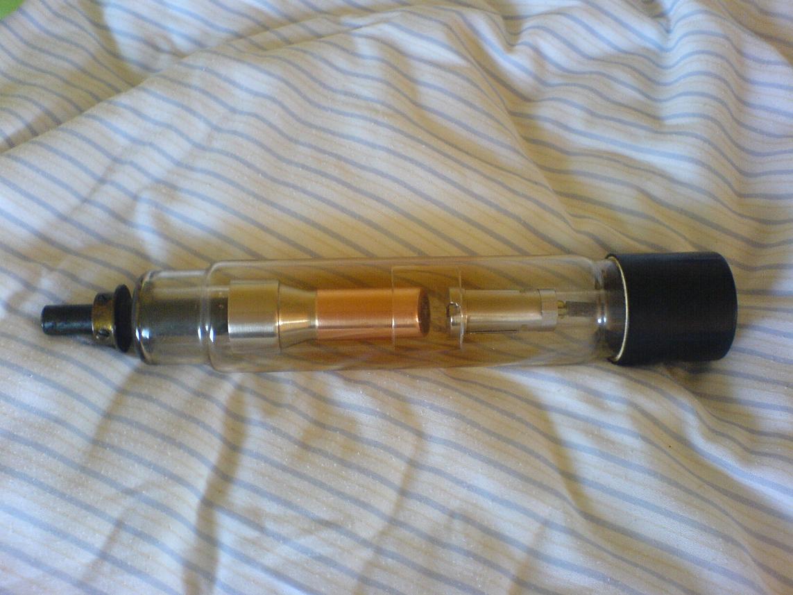
With
the X-ray tube passing current without breaking down, I assumed it was
radiating x-rays. Once again, my friend Harry provided by gifting me
with two quartz fiber dosimeters in the range of 200 and 500cGy. These
dosimeters have a small quartz fiber which is charged by the charging
unit. The charge leaks away incredibly slowly, and causes deflection of
the fiber much like in an electroscope.
I noticed no difference in the reading level even after a week had
passed, in fact both dosimeters are still at zero as I write this, and
it has been weeks since I charged them last. Ionizing radiation will
ionize gas molecules in the chamber however, and accelerate the charge
leakage rate. The amount of leaked charge can be read directly in the
dosimeter, and is calibrated to correspond to a set amount of ionizing
radiation. I proceeded to irradiate the dosimeters at different
positions relative to the tube, which would tell me where the x-ray
intensity is greatest and where points of low x-ray intensity exist.
Irradiating the dosimeters in the main beam at various distances
allowed me to determine the average dose based on the inverse
square
law. At 2mA, 65kV and just 7cm
from the anode spot the dose was
measured to be 108 Gy/hr. With this is defined as Io, the corresponding
radiation measurements matched up pretty well. You can see for yourself
how much distance helps reduce dose by using the inverse square law. At
a right angle to the tube, facing the user, the dose was measured to be
roughly half under the same conditions. Directly above the tube the
dose was measured to be ~0. Whether the x-rays are actually focused
somehow or the anode simply shields them I'm unsure, though I'd bet
it's the anode that's shielding.
With x-rays confirmed the next step is to attempt taking radiograms.
X-rays themselves can expose photographic paper, but at a very slow
rate. To help reduce the dose to patients, intensifying screens are
used, which consist of a phosphor coated screen. The phosphors will
fluoresce when exposed to x-rays, and create enough visible light to
greatly speed up the exposure rate. An intensifying screen will
fluoresce enough under a Coolidge tube to appear visible to the naked
eye in low light conditions. Intensifying screens can be purchased as
x-ray cassettes from hospitals upgrading their equipment. The benefit
of using a complete x-ray cassette is that it simplifies exposing
photopaper, as the cassettes are light-proof when closed, allowing
x-ray exposures regardless of the ambient light conditions. For taking
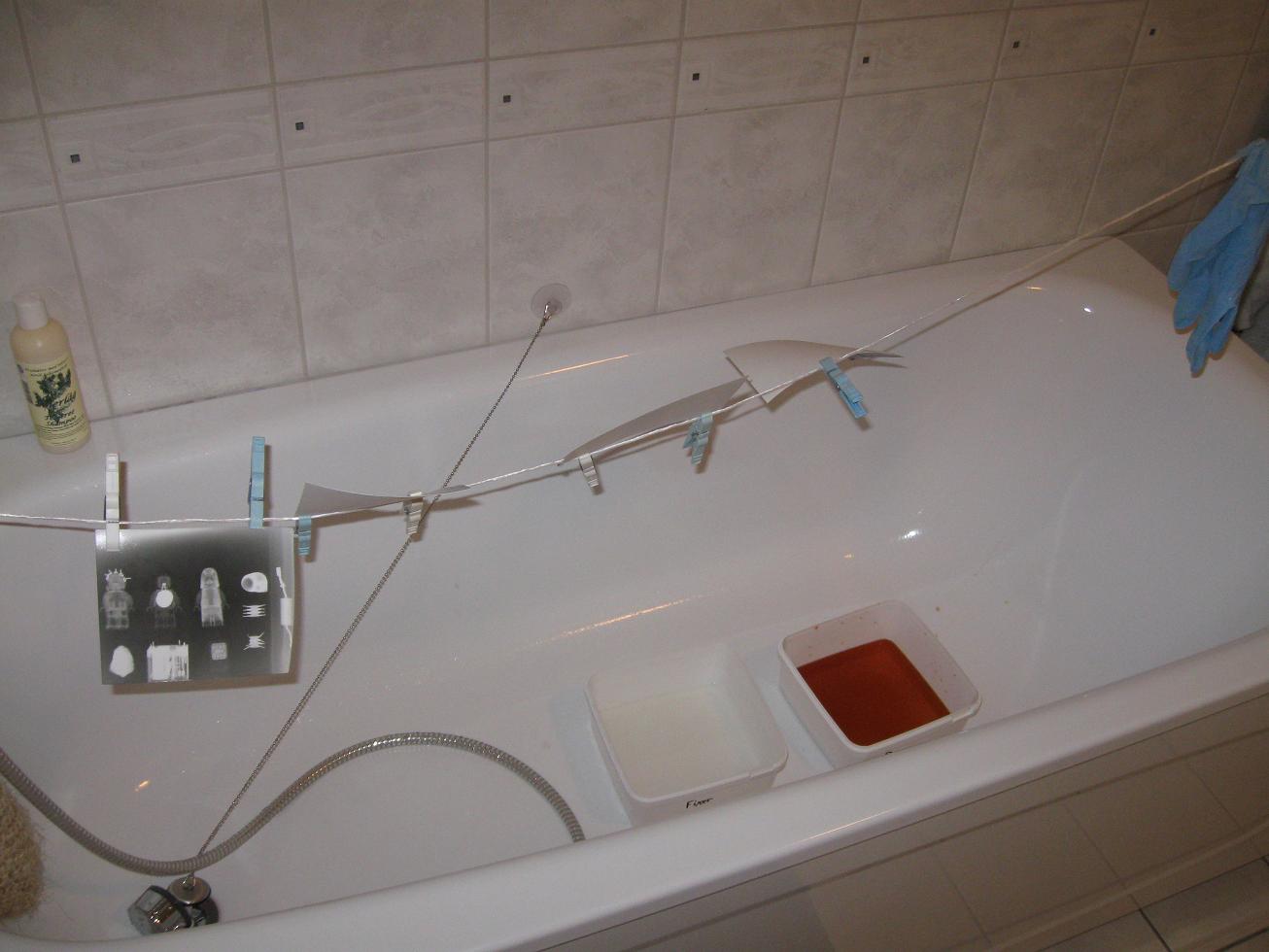
x-rays I had to learn basic photographic processing, which wasn't as
hard as I thought. A bathroom was converted into a darkroom by taping
cardboard over the one window in the room. I used some old ice-cream
containers as chemical trays, and opted to simply use developer and
fixer chemicals for processing of the images. I used Ilford Developer,
Ilford Rapid fixer and Fotokjemika EMAKS resin-coated fiber paper for
all of the photographies. The photographic paper was soaked in the
developer for 2-7 minutes, rinsed, soaked in the fixer for 2 minutes
and rinsed again. After they had dried I scanned them into my PC. In
the above picture the developer appears amber, when fresh it's clear.
The photographic paper was cut into smaller sheets, and exposed between
20 and 60s at roughly 2mA. The first batch of radiograms I took were at
reduced anode voltage, just 50kV. Due to most of the x-rays being in
the 30-40kV range, the penetration was low enough to show details in
plastic objects. I only took 4 x-rays at 50kV, and only one of them is
interesting. It's evident I needed some practice placing the objects
correctly, but otherwise it's a successful x-ray. The white spot in the
one Lego figure is the shadow cast by a small button cell battery, you
can also see a LED in the Lego figure's head. The exposure time was
35s, and the distance from the anode was 15cm. The x-rays were hardly
penetrating, and the image is almost under-exposed. For this reason I
upgraded the CW tower from four to six stages in order to increase the
anode voltage. I then proceeded to take some more x-rays, which turned
out considerably better. The white specs on the x-rays are from dust in
my scanner.
The 500cGy dosimeter, three sea shells, a rechargeable battery, an Ipod
nano and a 0.5 mm steel transformer lamination were x-rayed. The
exposure time was 30s at 15cm distance, 2mA of current and 70kV. The
paper is much more exposed than in the previous x-ray, showing that the
intensity of x-rays passing the glass wall of the tube has increased
considerably. The x-rays pass the aluminum housing of the dosimeter
with ease, while the steel lamination and Ipod backing are harder
targets.
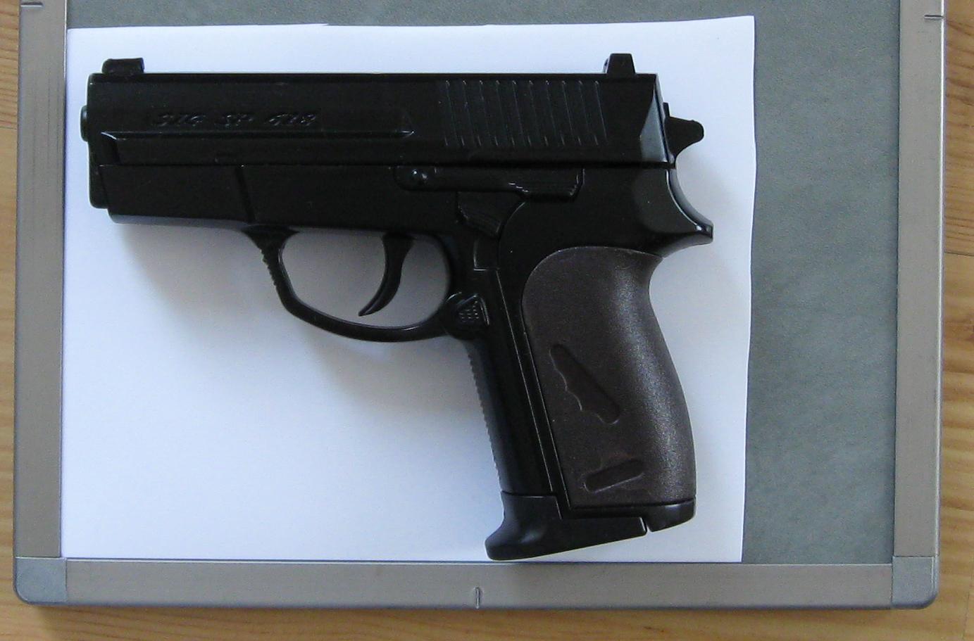
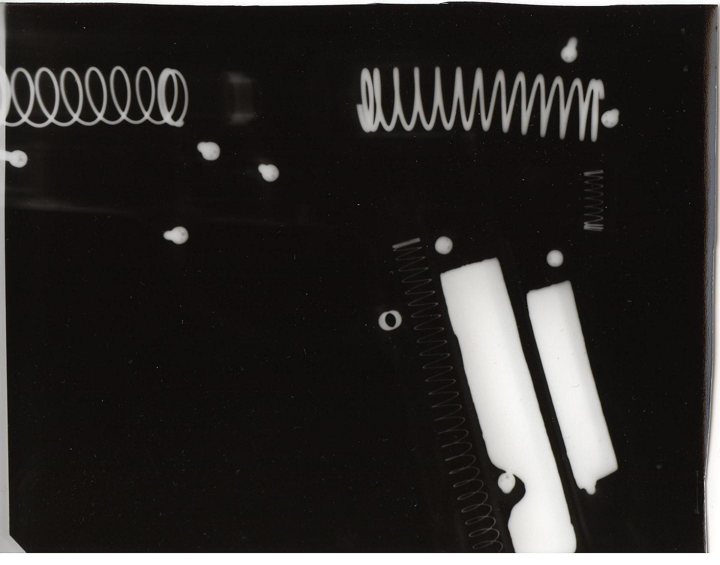
X-rayed here is a cheap soft gun for shooting plastic BBs. At 70kV the
plastic housing doesn't even show up. The exposure time was 51s at
15cm, I'm not sure why I left it for so long. Lead weights are used to
make these soft guns seem more authentic, and are easily visible in the
x-ray.
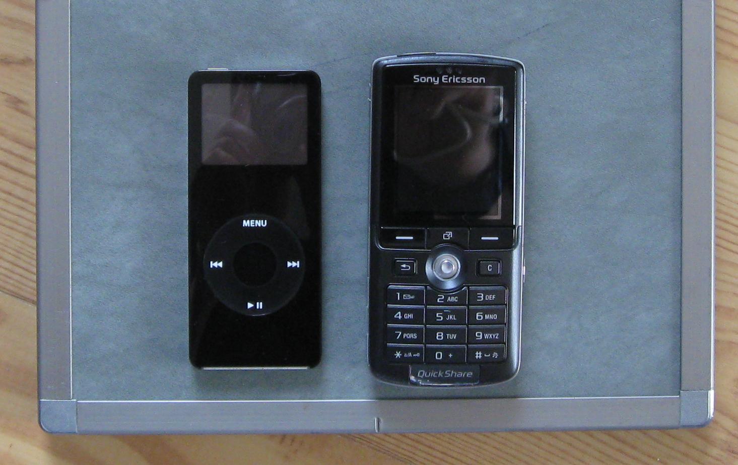
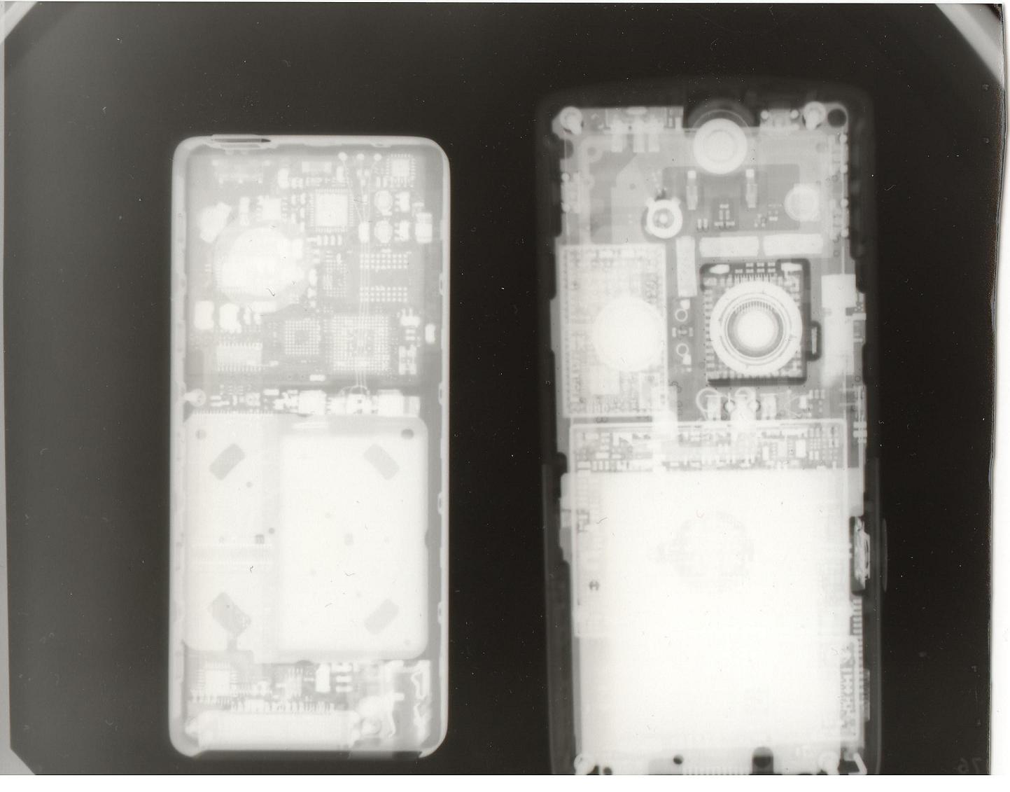
Here's the ipod again and a k750i cell phone. I used a thin, tin filter
during this exposure to help increase contrast. I also exposed the
image for 61s, the longest exposure yet.
This time it's the voltage multiplier unit from a color TV which
had an
old fashioned AC flyback inside, a digital watch and the 200cGy
dosimeter. I also took a close up x-ray of the anode, to see how large
the focal spot is. A small neodymium magnet was placed approximately
under the center of the anode for reference. Due to the shield and
cassette size I couldn't get close enough for a real good image, but
it's close enough to give an outline of the main
beam area. Above the
magnet one can see the sharp shadow from the "anode heel effect". The
tilt is probably due to the anode and cassette not being precisely
parallel. As is visible from the exposure, the intensity diminishes
rapidly behind the anode and to some extent behind the cathode. Out to
the sides the intensity gradually decreases, but doesn't really become
negligible until directly above the anode. I didn't use a filter for
the image, and judging by checks with my dosimeter most of the higher
energy x-rays are radiated in a wider angle than the image would
suggest.
As of the time of writing this I've put the x-ray machine away, as it
lacks proper shielding. I currently plan on upgrading it so the tube is
completely encased in lead, and cooled by some means. Even a one minute
exposure can overheat the tube, and it takes several hours for it to
dissipate the heat as it can only radiate it as infrared. Almost all of
the energy used to make x-rays is lost as heat, save the 1% mentioned
earlier, so for continuous operation the anode would have to get rid
off 100 - 300W of power depending on the anode current. That would
require heatsinking of the anode, which is difficult considering the
immense voltage present on it. As for the current steel shield, it
may seem adequate, but many x-rays are reflected from nearby objects
and can significantly increase one's radiation dose. Before I do any
further experimentation I'll need proper shielding which reduces the
risk of scattered x-rays.
Want more? See these
Amateur X-ray projects as well:
Disclaimer:
I do not take responsibility for any injury, death, hurt ego, or other
forms of personal damage which may result from recreating these
experiments. Projects are merely presented as a source of inspiration,
and should only be conducted by responsible individuals, or under the
supervision of responsible individuals. It is your own life, so proceed
at your own risk! All projects are for noncommercial use only.

 little use. However I had no way to tell if the tube
still held a vacuum, so my 75USD might simply have paid for an
expensive, but awesome paper weight. So I asked a technician at
ritterdental.com for
some specs on the tube, which were given. What I got suggested the tube
works in the range of 40 - 70kV, at anode currents from 0 - 15mA. Still
nothing about the filament voltage/current though, so I had to tread
cautiously to avoid burning the filament. Before doing anything I
connected the tube to a "low" high voltage supply (old AC flyback at
30kV) which would reveal the presence of gas. If the tube lights up or
shows a visible arc it has leaked and cannot be used for x-rays. I
checked the tube's vacuum before driving the filament, as driving a
filament without a vacuum would have burned the it. To drive the
filament I eventually settled on a simple linear regulator, the LM338T
and empirically determined the correct voltage range for my filament.
This was done by slowly increasing
the filament voltage with high voltage on the anode, until the tube
started to conduct. After several measurements of the filament voltage
and anode current I determined that the filament needed to operate
between 3
and 4V, which is roughly the norm for Coolidge
X-ray tubes. The exact
filament voltage is crucial, as once the tube starts conducting more
than 1mA even tiny changes in the filament temperature greatly increase
the anode current. For all practical purposes constant voltage will
work when driving the filament, either AC or DC. To the left is the
basic circuit I used for providing test voltages for the filament. The
1k potentiometer was later changed for a smaller value and a fixed
resistor to decrease the adjustment range and provide greater
control
over the voltage.
little use. However I had no way to tell if the tube
still held a vacuum, so my 75USD might simply have paid for an
expensive, but awesome paper weight. So I asked a technician at
ritterdental.com for
some specs on the tube, which were given. What I got suggested the tube
works in the range of 40 - 70kV, at anode currents from 0 - 15mA. Still
nothing about the filament voltage/current though, so I had to tread
cautiously to avoid burning the filament. Before doing anything I
connected the tube to a "low" high voltage supply (old AC flyback at
30kV) which would reveal the presence of gas. If the tube lights up or
shows a visible arc it has leaked and cannot be used for x-rays. I
checked the tube's vacuum before driving the filament, as driving a
filament without a vacuum would have burned the it. To drive the
filament I eventually settled on a simple linear regulator, the LM338T
and empirically determined the correct voltage range for my filament.
This was done by slowly increasing
the filament voltage with high voltage on the anode, until the tube
started to conduct. After several measurements of the filament voltage
and anode current I determined that the filament needed to operate
between 3
and 4V, which is roughly the norm for Coolidge
X-ray tubes. The exact
filament voltage is crucial, as once the tube starts conducting more
than 1mA even tiny changes in the filament temperature greatly increase
the anode current. For all practical purposes constant voltage will
work when driving the filament, either AC or DC. To the left is the
basic circuit I used for providing test voltages for the filament. The
1k potentiometer was later changed for a smaller value and a fixed
resistor to decrease the adjustment range and provide greater
control
over the voltage.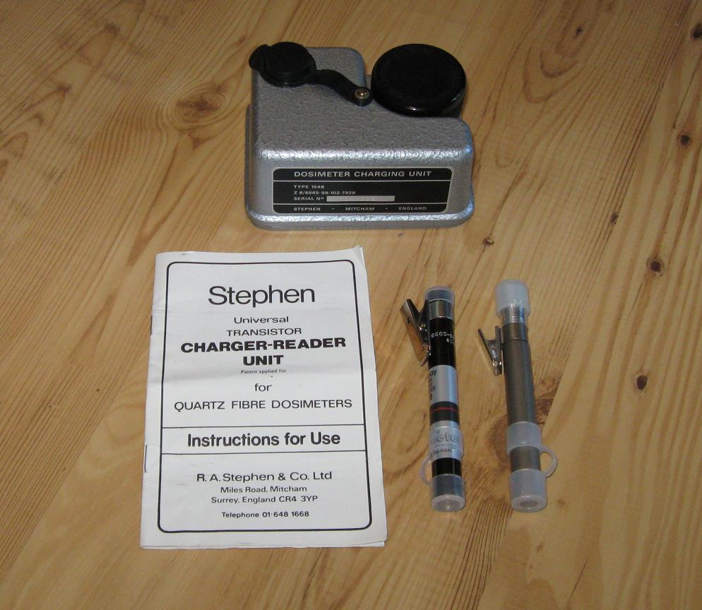
 main
beam area. Above the
magnet one can see the sharp shadow from the "anode heel effect". The
tilt is probably due to the anode and cassette not being precisely
parallel. As is visible from the exposure, the intensity diminishes
rapidly behind the anode and to some extent behind the cathode. Out to
the sides the intensity gradually decreases, but doesn't really become
negligible until directly above the anode. I didn't use a filter for
the image, and judging by checks with my dosimeter most of the higher
energy x-rays are radiated in a wider angle than the image would
suggest.
main
beam area. Above the
magnet one can see the sharp shadow from the "anode heel effect". The
tilt is probably due to the anode and cassette not being precisely
parallel. As is visible from the exposure, the intensity diminishes
rapidly behind the anode and to some extent behind the cathode. Out to
the sides the intensity gradually decreases, but doesn't really become
negligible until directly above the anode. I didn't use a filter for
the image, and judging by checks with my dosimeter most of the higher
energy x-rays are radiated in a wider angle than the image would
suggest. This work is licensed under a
Creative Commons Attribution-Noncommercial-Share Alike 3.0 Unported License.
This work is licensed under a
Creative Commons Attribution-Noncommercial-Share Alike 3.0 Unported License.