Using flyback transformers in ways they were never intended to be used
eventually leads to failure of the transformer. Fortunately the core
almost always remains intact, and can be salvaged to make a new transformer. I've
tried several times to make my own flybacks, but each attempt has been
unsuccessful until now. I finally seem to have developed a
relatively easy method, which creates good HV resistant transformers. This is what
must be kept in mind:
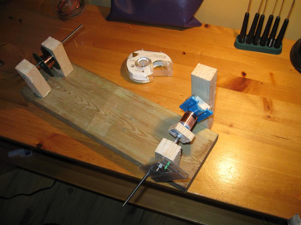
Insulate the layers with
something stiff and HV resistant. I use
overhead transparencies, which can stand some 14kV per sheet IIRC. Use
good insulating tape to hold things in place, but do not overdo. It's
important to leave enough space between the top and bottom
oflayers to prevent arc-overs between layers.
When terminating a layer,
bring the wire back to the start of the
winding before continuing on the next layer. Insulate as required, both
before crossing back and after, before starting on the next layer. This
reduces interwinding capacitance.
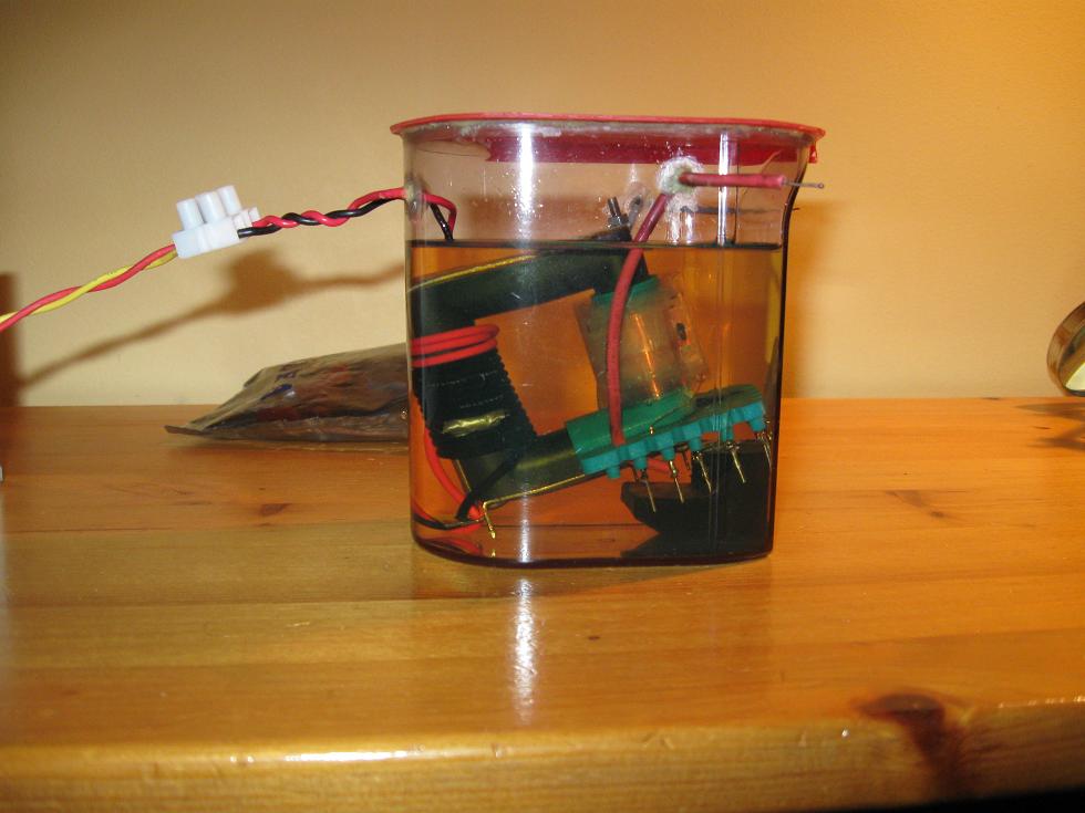
Submerge in oil or vacuum
pot. This is to prevent corona from eating
away at the insulation and eventually destroying the transformer. Oil
is the easiest for a hobbyist to use, as it just takes a container and
some
oil. Cooking oils are supposed to be pretty good, and are actually used
in some power transformers. I use mineral oil however, so I don't need
to worry about it going rancid. Standard hydraulic oil has worked well
for me.
Use single strand wire for the primary, or you'll have problems with oil seeping out of the wire by capillary action!
That should have the most important points covered. As for the number
of turns, base it on the size of the core, drive frequency and desired
output voltage. The core size and frequency will dictate a minimum
amount of primary turns, and the supply- and desired output voltage a
turns ratio. The math behind this is the same as when winding GDTs,
here's a link to
the calculator. An important note: I used 500 secondary turns in my
transformer and 14 primary turns. Driven from my half-bridge this
should give 5kV out, but it gave 10kV. This is
dueself-resonance
and parasitic L and C components causing ringing on the output. So you
can almost count on twice the output voltage that turns ratio alone
would predict. For my transformer I used a wimpy AC flyback core from a
xfrmr which had previously arced-over. Given the overall size of the
new secondary winding, a standard DC flyback core would have worked
just as well. When picking a driving frequency it's important to note
that the primary inductance is low (20-40µH), which results in a
good portion of magnetizing current being switched by the inverter.
Increasing the drive frequency reduces the magnetizing current. This
can also be countered by using an external air core ballast inductor of
some 20µH, and tuning for the parallel resonant frequency of the
transformer. The parasitic capacitance on the secondary side is squared
when seen at the primary, resulting in considerable parallel
capacitance. The exact resonant frequency can be found by placing a
small lightbulb in series with the primary, and tuning the frequency
until a minimum in lightbulb brightness is found. Without a ballast
inductor, the square-wave voltage-source inverterlike
any half- or full-bridge would suffer huge losses. (Remember that square
waves consist of several sine wave harmonics, and each harmonic above the
resonant frequency sees an increasingly smaller impedance.) With the
ballast inductor however each rising harmonic sees an increasing
inductive impedance, sparing the inverter.
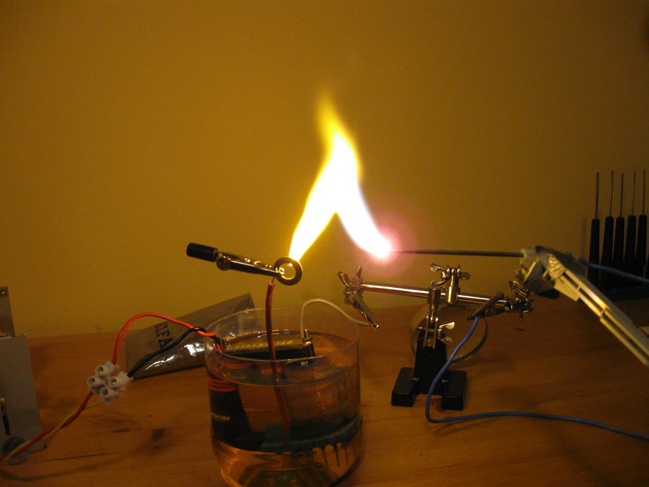
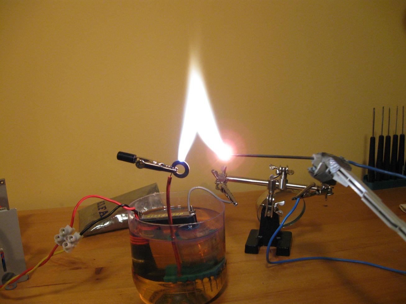
Driven from my Multipurpose Inverter. Arcs start at 1cm.
Youtube Video!
The Big Mofo HV Transformer
I won this core for an excellent price on ebay, and originally I was
planning on using it in a SLR inverter for charging large
high voltage capacitor banks. However due to failure in getting SLR to
work properly I have been forced to hard-switch the transformer for the
time being. That doesn't prevent awesomeness however, and this
transformer can supply some real power despite being run well below
it's capabilities. It's specs are 15.2 cm tall x 9.3 cm long x 3.0cm
wide, core material N27 and 880mm^2 of cross-sectional area. Quite the
mammoth compared to the "little" flyback cores I'm used to seeing.
Currently driven by the Multipurpose Inverter Mega
(which is much tooweak) at 120 - 145kHz and 100% duty. During
initial
tests with this transformer capacitive coupling to the core were
causing large amounts of corona and eating away at the PVC secondary
former. This puzzled me as the output voltage should only have been
10kV on each leg and the clearance seemed to be enough. I later learned
that the open circuit voltage is up to FOUR times greater than
predicted,due to unknown effects of stray reactive components
and presumably parallel resonance. The design goal of this transformer
became to power my CW Tower to create a 80kV DC supply, at substantial
power. After some testing and many failed configurations I determined
that a turns ratio of only 1:15 would provide roughly 20kV of output
voltage. I opted for 15 primary turns and 225 secondary
turns.The transformer was purposely wound to maximize leakage
inductance which helps limit current when drawing arcs, so each winding
was wound on separate limbs of the core. Given the tendency of corona
formation I found myself forced to submerge the entire assembly under
oil.
Lichtenberg figures on the secondary coils from corona damage. This was before oil submersion.
Core assembly. The 8
turns shown in the picture are from the testing phase. Unlike
half-bridge drive where the voltage is twice what is expected, I found
the voltage to be 4 times the expected value. The current configuration
uses 15 primary turns, which fills the winding window better anyway.
Youtube Video!
(Video was taken during 8-pri turns configuration)
Disclaimer:
I do not take responsibility for any injury, death, hurt ego, or other
forms of personal damage which may result from recreating these
experiments. Projects are merely presented as a source of inspiration,
and should only be conducted by responsible individuals, or under the
supervision of responsible individuals. It is your own life, so proceed
at your own risk! All projects are for noncommercial use only.

 This work is licensed under a
Creative Commons Attribution-Noncommercial-Share Alike 3.0 Unported License.
This work is licensed under a
Creative Commons Attribution-Noncommercial-Share Alike 3.0 Unported License.