A reliable high power, high voltage source is something useful to have
kicking around for physics experiments, and after seeing a creative
design by Mates on the 4HV forum I decided to make my own voltage
multiplier. I started by
constucting a 4-stage model, but after a year I upgraded it with
another two stages for even greater voltages.
The circuit
is just a standard voltage multiplier, or 2-stage Cockcroft-Walton
multiplier, or Villard cascade depending on your favorite historical
inventor. It could also be called a Greinacher, but that's a marginally
different circuit so we'll keep it at CW for now. The circuit works by
alternating between charging up the left and right side
capacitors
up the ladder until they have all reached full potential. The
capacitors and diodes will have the twice the AC potential across them,
as in the voltage from negative to positive peak. Add some overhead for
safety, and you're left with 60kV ratings when using a 20kV source.
Such high voltage
ratings are easy to achieve with homemade materials however.
I used four strings times 60 RGP10M diodes, and four HV capacitors made
by Mate's
recipe. Construction was pretty
straight forward. First I
made the capacitors with tin foil and overhead transparencies. I made
sure to give at least 4cm of clearance from the sides so it wouldn't
arc over. Basically the capacitors are made by paralleling 5-6 overhead
transparency sheets, then putting one sheet of tin foil on top, another
5-6 overhead sheets, one more tin foil, then finally rolling together
and taping. The voltage standoff is surprisingly good given the quick
and cheap construction.
Then I moved on to the
diode stack. 240 diodes, and they all had to be chained together. It
took a few hours from I started until they were all linked together in
strings. I chose RGP10M diodes because my electronics source had them
in large quantity for a good price. Besides convenience, they are
avalanche rated which means if the voltage exceeds their rating they
can safely breakdown and dissipate a certain amount of energy. This is
necessary when putting diodes in series as it prevents a diode from
exploding if it is slightly mismatched and too much voltage is dropped
across it. The use of 60 diodes per string also give a decent safely
margin. RGP10Ms also have about 500ns of recovery time, which is
acceptable when using an input source up to 100kHz.
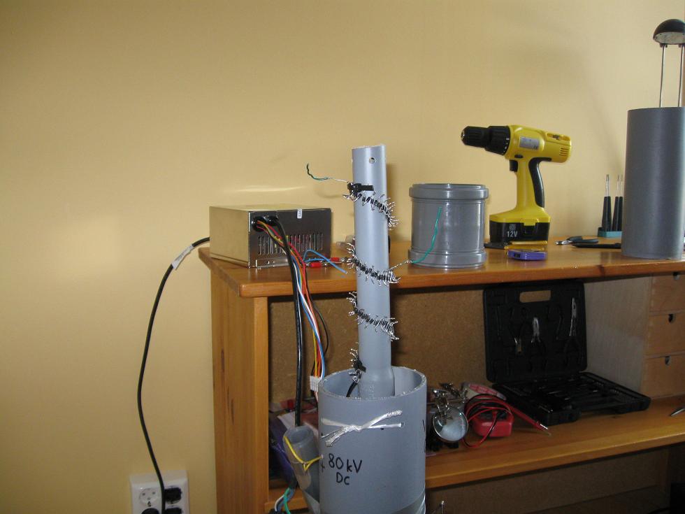
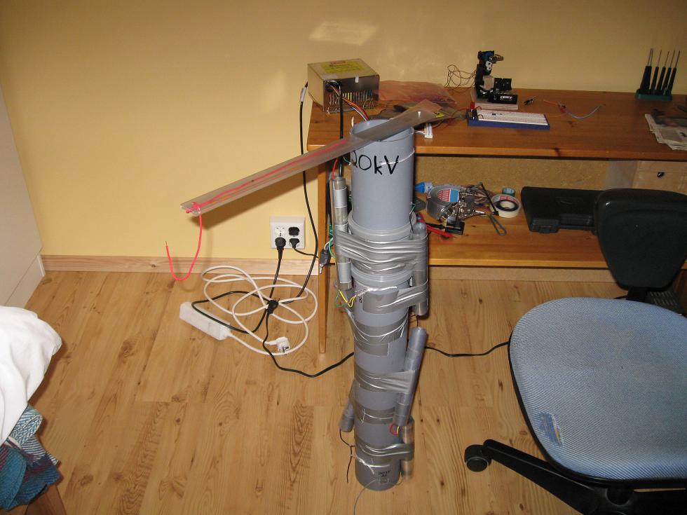
Here the diodes are spiraled around a thin PVC pipe to give them some
structure and voltage stand-off in a smaller package. Beside them is
the pipe they will soon be fitted into. The diode tower was centered
and suspended with twine within the main PVC pipe. Wires from the diode
tower were pulled through small holes in the large PVC
pipe. Some
duct-tape really eases
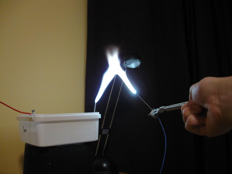
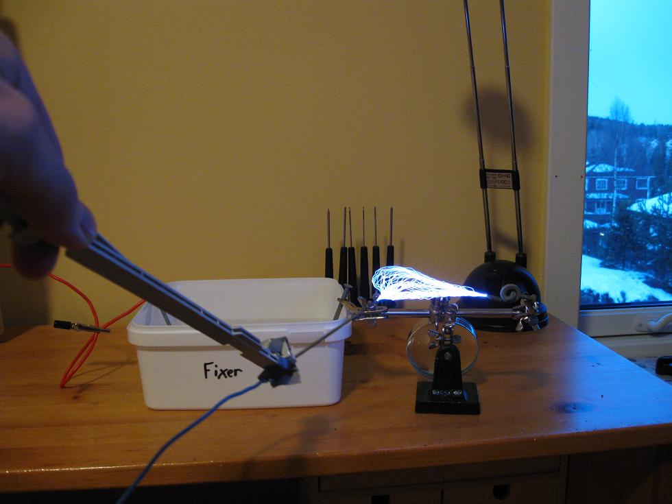
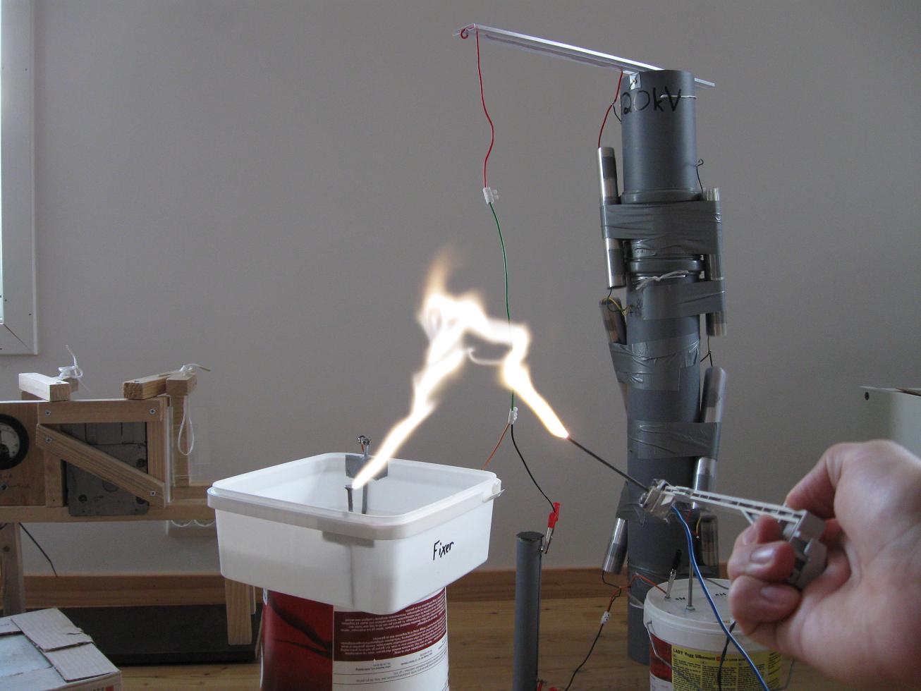
construction. Be sure to see the video as the pictures don't
do
justice, capturing a still photo of an arc at it's greatest is nearly
impossible. Remember when drawing arcs from a high voltage CW like
this, that care must be taken not to simply short the output leads
together. The capacitors are charged to about 40kV, and will dump all
of their energy into the spark and diodes at once, resulting in large
peak currents flowing through the diodes. For one thing it's
damaging to the diodes and will lead to failure. If the driver is too
weak it can also prevent an
arc from forming, as the capacitors will not have sufficient energy
left to sustain an arc, resulting in sparks instead.
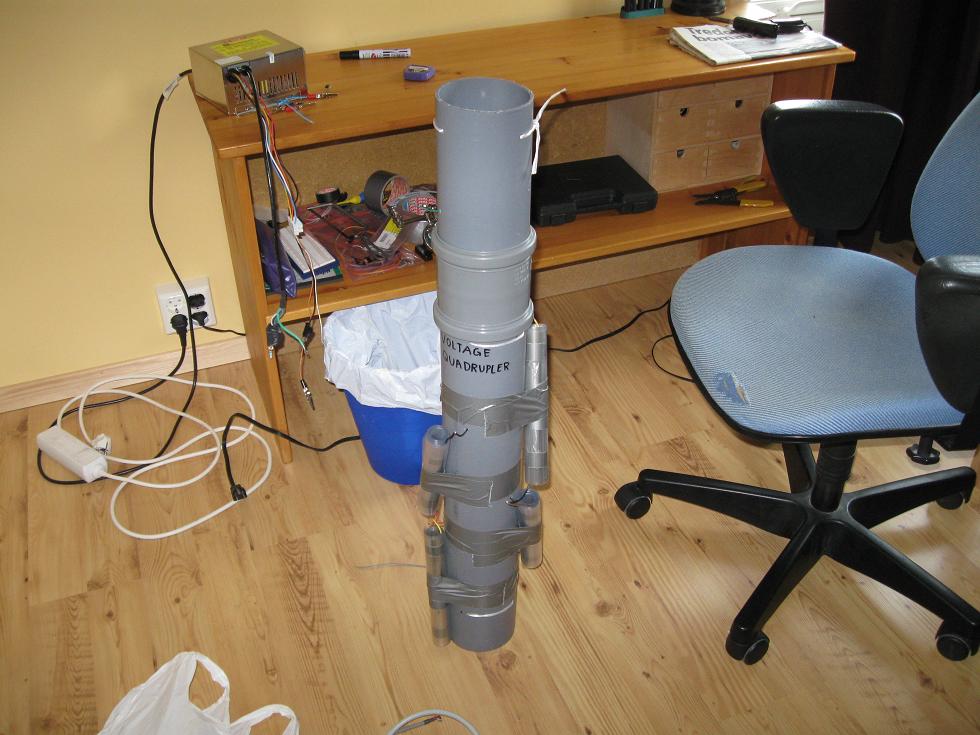
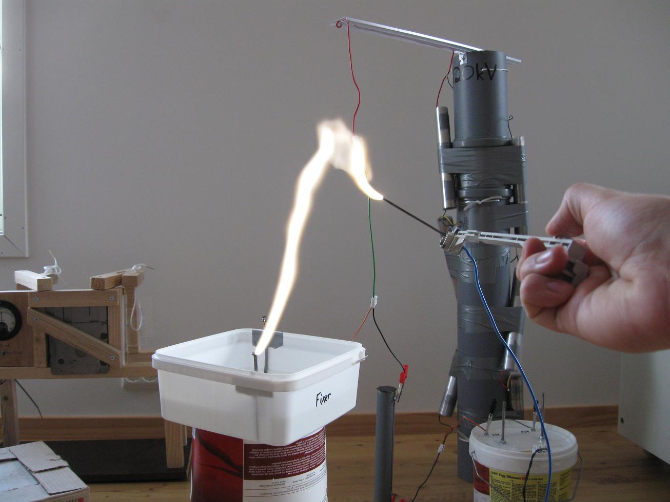
The
finished multiplier
and setup. The arc picture was taken just as a strike occurred, it can
be drawn out much further. the sparks were taken when the CW was driven
from my smaller 10kV homemade transformer. It was ballasted which
prevented arc formation unless the leads were brought within close
proximity to eachother.
Youtube Video!
Update! Now 120kV CW Tower
In order to provide the required voltage for my Coolidge X-ray tube I
had to add another two stages to the Cockcroft–Walton Tower.
With
some handy plumbing parts and some more duct-tape it was a breeze to
upgrade. The beauty of multipliers is their ease of scaling up with
more stages. In conjunction with my recent X-ray experiments,
I've measured the voltage from the CW multiplier without load, powered
from the
Big-Mofo transformer. It turns out the voltage from the transformer is
only about 13kV. Meaning in the above video the voltage was really
50kV, not 80kV as thought previously. With the two extra stages it's
now
75kV no load. The pictures speak for themselves, the upgrade only took
an afternoon of work. When drawing arcs the power consumed is over
1,5kW!
And
of course a video:
Disclaimer:
I do not take responsibility for any injury, death, hurt ego, or other
forms of personal damage which may result from recreating these
experiments. Projects are merely presented as a source of inspiration,
and should only be conducted by responsible individuals, or under the
supervision of responsible individuals. It is your own life, so proceed
at your own risk! All projects are for noncommercial use only.

 This work is licensed under a
Creative Commons Attribution-Noncommercial-Share Alike 3.0 Unported License.
This work is licensed under a
Creative Commons Attribution-Noncommercial-Share Alike 3.0 Unported License.