
Multi-purpose Inverter
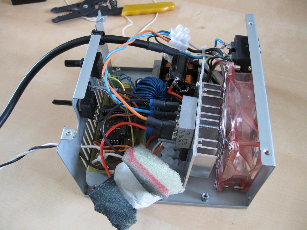
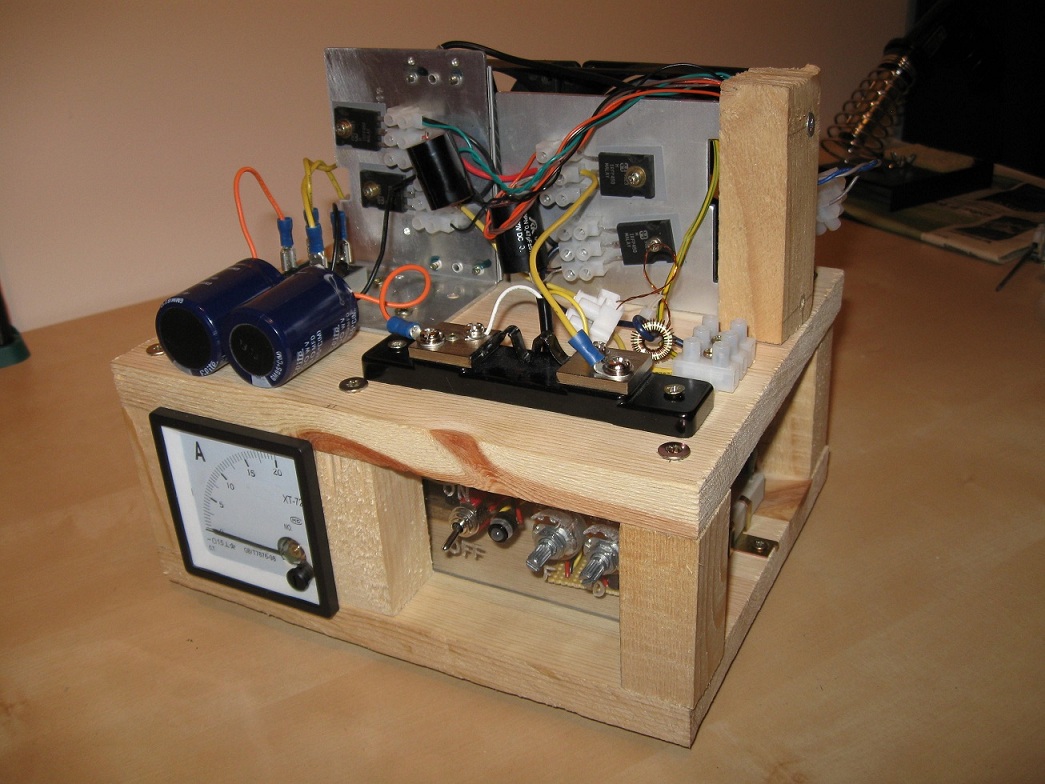
Ever notice how many projects use the same sort of oscillator -> gate driver -> half-bridge setup? If not, flybacks, induction heaters and SSTCs are what I'm thinking of. Since they can all use the same basic driver why not make one universal driver to use for all these projects? Fueled by this thought I made a TL494 based oscillator which has separate pulse width and frequency control. This then runs a simple gate driver stage and finally a half-bridge. To ensure that I could keep mosfet deaths to a minimum I put some safety features in place. First a primary current detection transformer is used to monitor the current through the load, and shut down the inverter if some threshold is reached. Second a thermistor is placed directly on one of the mosfets to monitor their current temperature, again once a threshold is reached the inverter is shut down. This eliminated two major causes of catastrophic failure, though that's not to say things don't still go wrong. ;-) This driver was used in my offline flyback driver, and is basis of the breadboarded driver used in the series resonant induction heater setup. I now use my multi-inverter for both projects whenever I need a quick demonstration.
 I've
designed a PCB for this project, and the files can be
downloaded here.
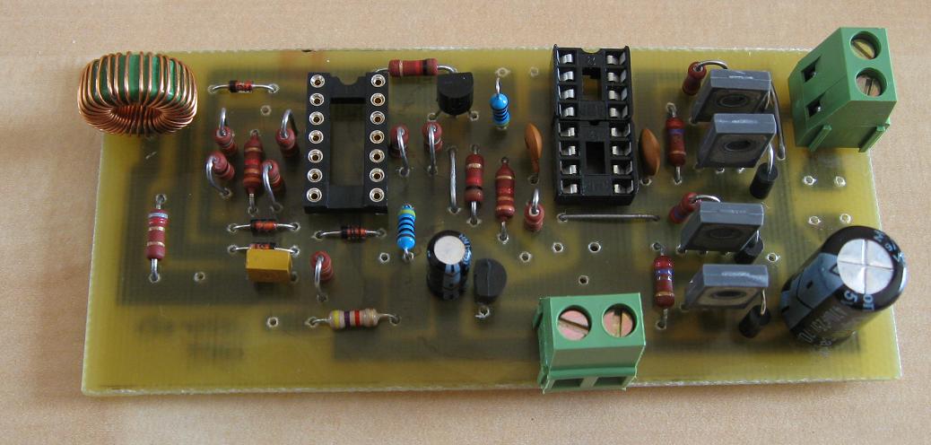
The PCB in the image is of revision 1, which had some errors in the
shutdown circuitry caused by the LM324 not swinging above 3,5V. The
errors are fixed now, hence the different appearance of the PCB
layout in the zip.
Not
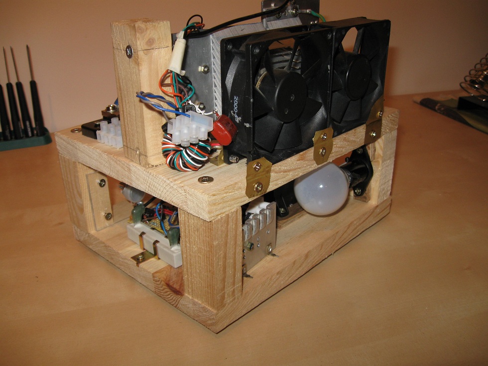
specified in the schematic are heatsink requirements. When switching a
14A load the IRFP450s will dissipate a total of 85W, and on top of that
the rectifier will contribute
with another 5W or so. In comparison the average PC draws
120W, most of which is turned into heat. This power needs to be removed
somehow, and we know how much effort goes into cooling a
PC. Though my setup isn't ideal, it's not designed for
continuous use so the puny fan/heatsink should suffice. Another
unmentioned aspect is construction of the GDT (gate drive
transformer) and CT (current transformer). Since it's used in so many
projects I've made a small article about them, which you can read here.
I usually scavenge CTs from ATX supplies and adjust the number of turns
to my requirements. When purchasing one however the same points apply
as when selecting a GDT core.
I've
designed a PCB for this project, and the files can be
downloaded here.
The PCB in the image is of revision 1, which had some errors in the
shutdown circuitry caused by the LM324 not swinging above 3,5V. The
errors are fixed now, hence the different appearance of the PCB
layout in the zip.
Not
specified in the schematic are heatsink requirements. When switching a
14A load the IRFP450s will dissipate a total of 85W, and on top of that
the rectifier will contribute
with another 5W or so. In comparison the average PC draws
120W, most of which is turned into heat. This power needs to be removed
somehow, and we know how much effort goes into cooling a
PC. Though my setup isn't ideal, it's not designed for
continuous use so the puny fan/heatsink should suffice. Another
unmentioned aspect is construction of the GDT (gate drive
transformer) and CT (current transformer). Since it's used in so many
projects I've made a small article about them, which you can read here.
I usually scavenge CTs from ATX supplies and adjust the number of turns
to my requirements. When purchasing one however the same points apply
as when selecting a GDT core.
![]()
![]()
![]()
![]()
Disclaimer: I do not take responsibility for any injury, death, hurt ego, or other forms of personal damage which may result from recreating these experiments. Projects are merely presented as a source of inspiration, and should only be conducted by responsible individuals, or under the supervision of responsible individuals. It is your own life, so proceed at your own risk! All projects are for noncommercial use only.
 This work is licensed under a
Creative Commons Attribution-Noncommercial-Share Alike 3.0 Unported License.
This work is licensed under a
Creative Commons Attribution-Noncommercial-Share Alike 3.0 Unported License.
4518 unique visitors since 28th June 2020.