This project was created out of necessity while I was getting into
making PCBs. I need a source of UV light to expose photoresist boards,
so it was time to get creative. I had seen people use UV tubes,
ballasts and the works to make
something just like you can buy from a shop, but why? These days UV
LEDs are cheap as dirt, and many times more efficient. A quick search
on ebay revealed several lots of 100x UV LEDs from Asia (with FREE
shipping!) for half the price of one UV tube. If that isn't awesome
enough, the UV LEDs will last nearly indefinitely if used properly, and
generate nearly no heat. So it's easier to use and eco friendly.
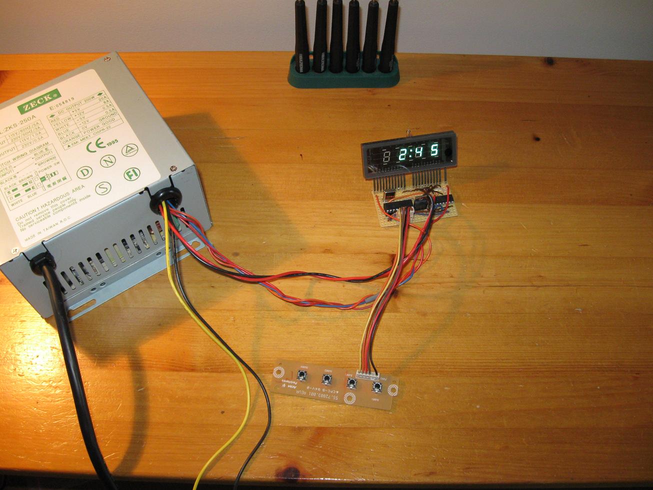
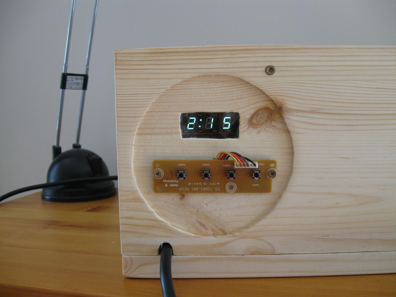
While waiting for the LEDs to arrive I figured a timer would be nice so
I could do consistent exposures. I still had a VFD from a gutted
microwave oven, an old PIC16F84A and a bunch of switches soldered to a
PCB from a monitor. What more could I ask for? Some programing later I
had a functional timer, which would automatically control the UV LEDs,
and remember the exposure time last used. I decided to use a A6810
shift register/VFD driver to free up some I/O pins. I'm glad I did, as
the VFD is considerably brighter than the discrete driver I built for
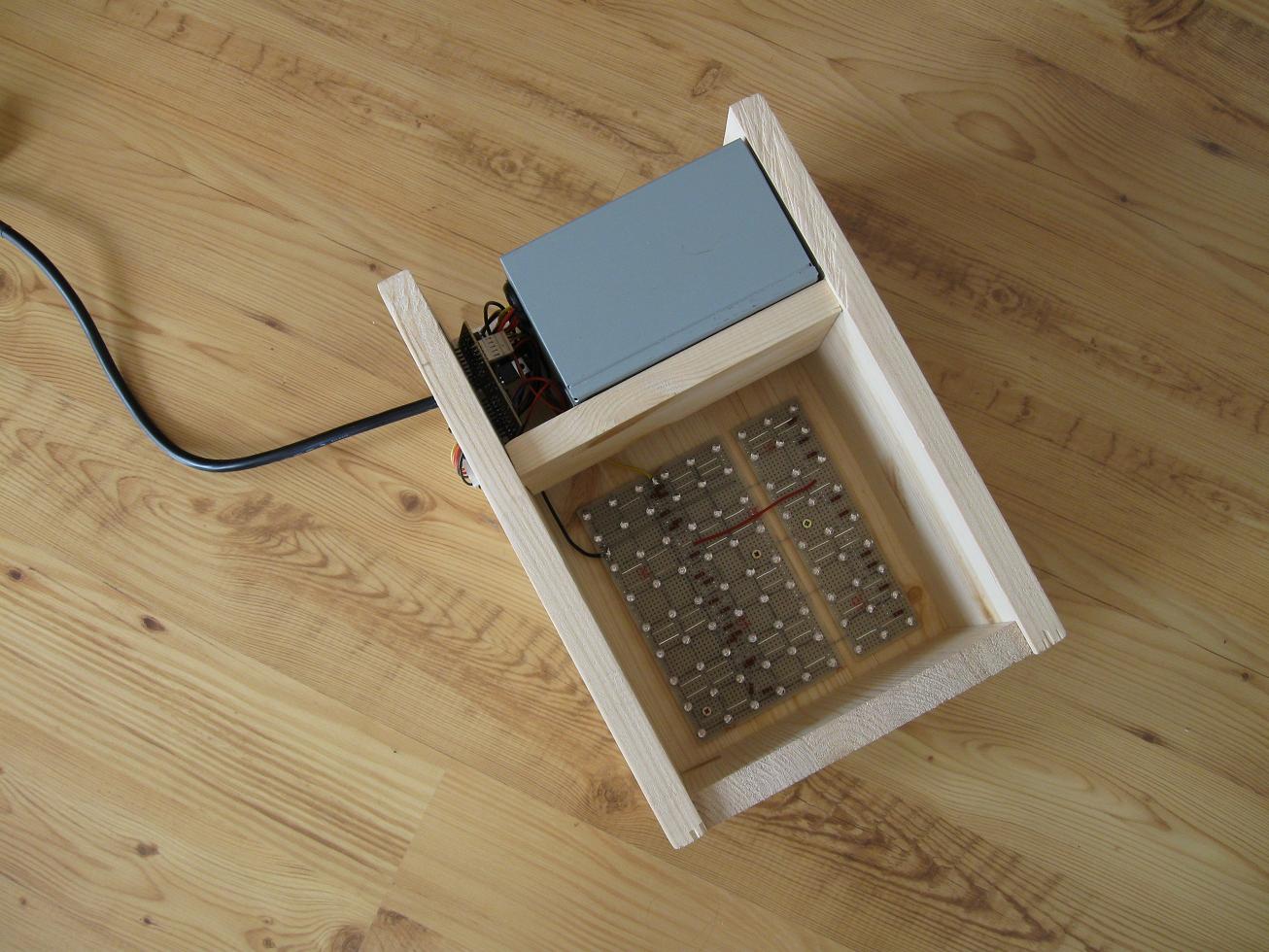
my AVR Chronograph. I also used the original transformer to power the
VFD, it's glued in the AT box which is why you can't see it. Firmware
and schematic can be downloaded here: UV LED
Developer Box.zip
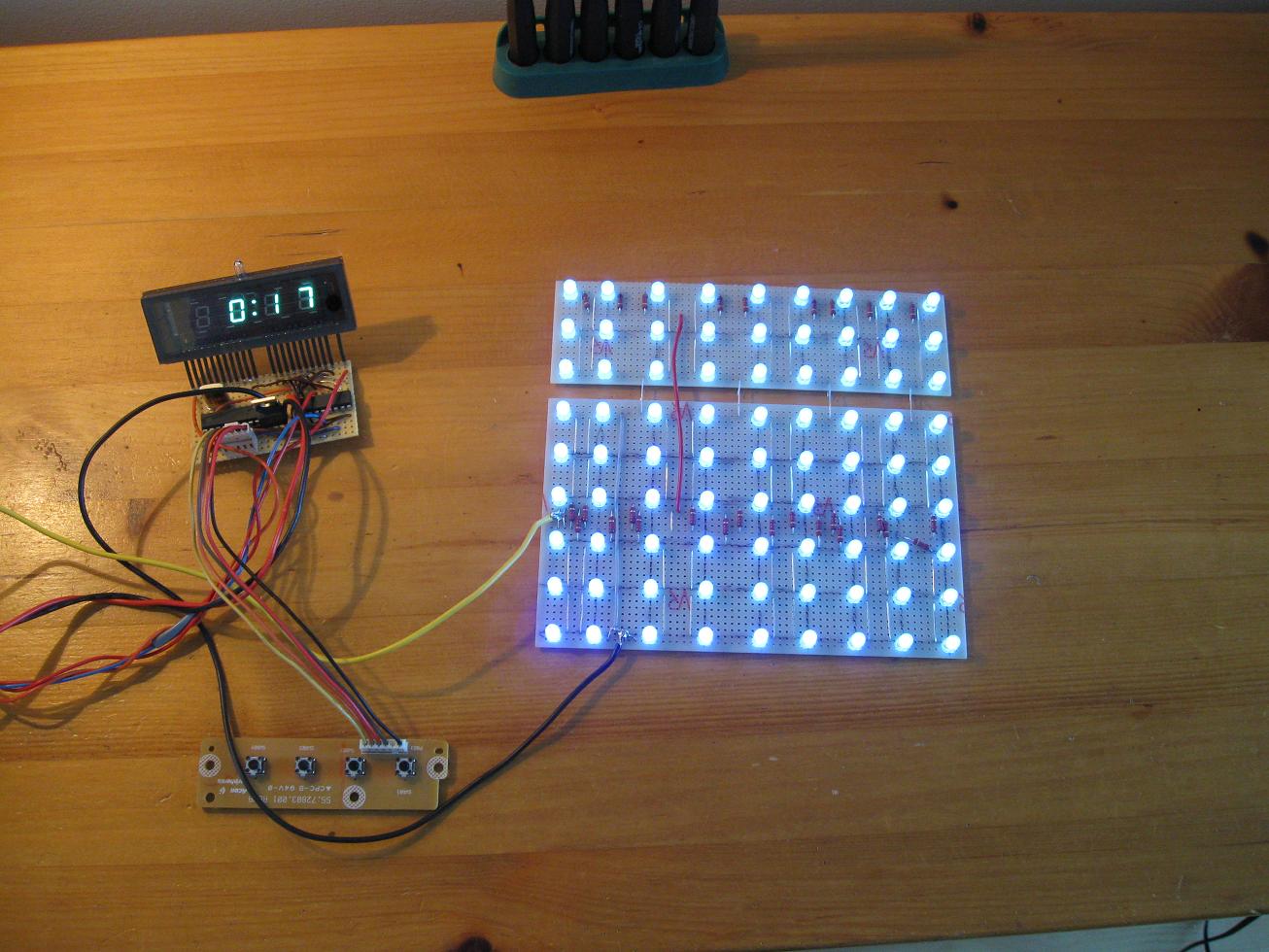
I decided to use 12V for the UV LEDs, as this would work fine with the
old AT supply I decided to dedicate to this project. Each LED has a
Vdrop of about 3.5V, which means I'll use 3 in series for 10.5V, so
only 1.5V will be wasted in the current limiting resistor. Using an
individual resistor for each LED is a waste of power, time and
resources. I decided to fill a 16x 16cm matrix with LEDs, so rather
large boards could be exposed. It would also make the most use of the
100 LEDs I had. The LEDs were mounted on standard stripboard, with
about
2cm spacing.
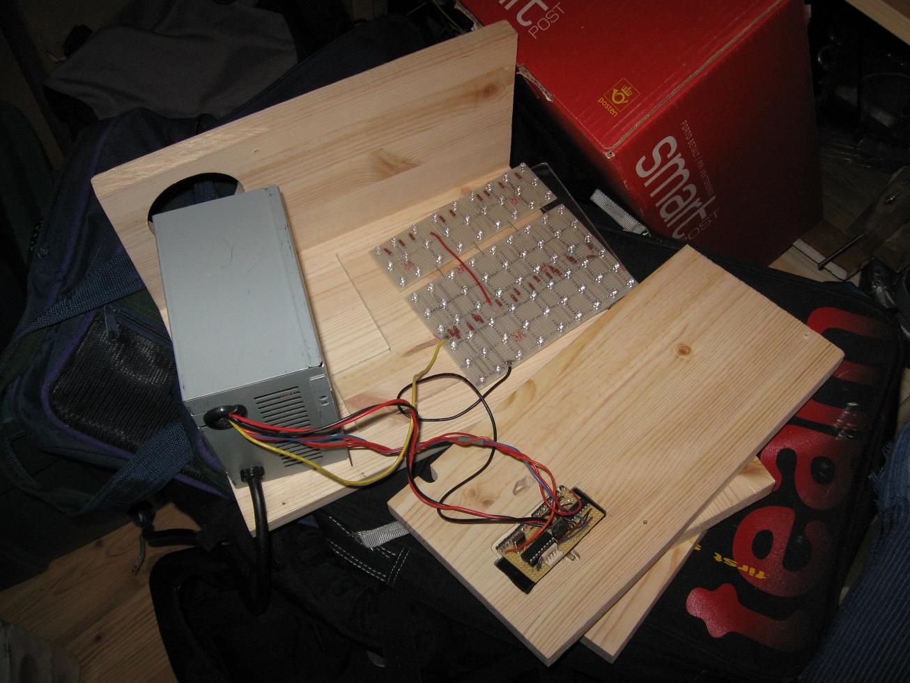
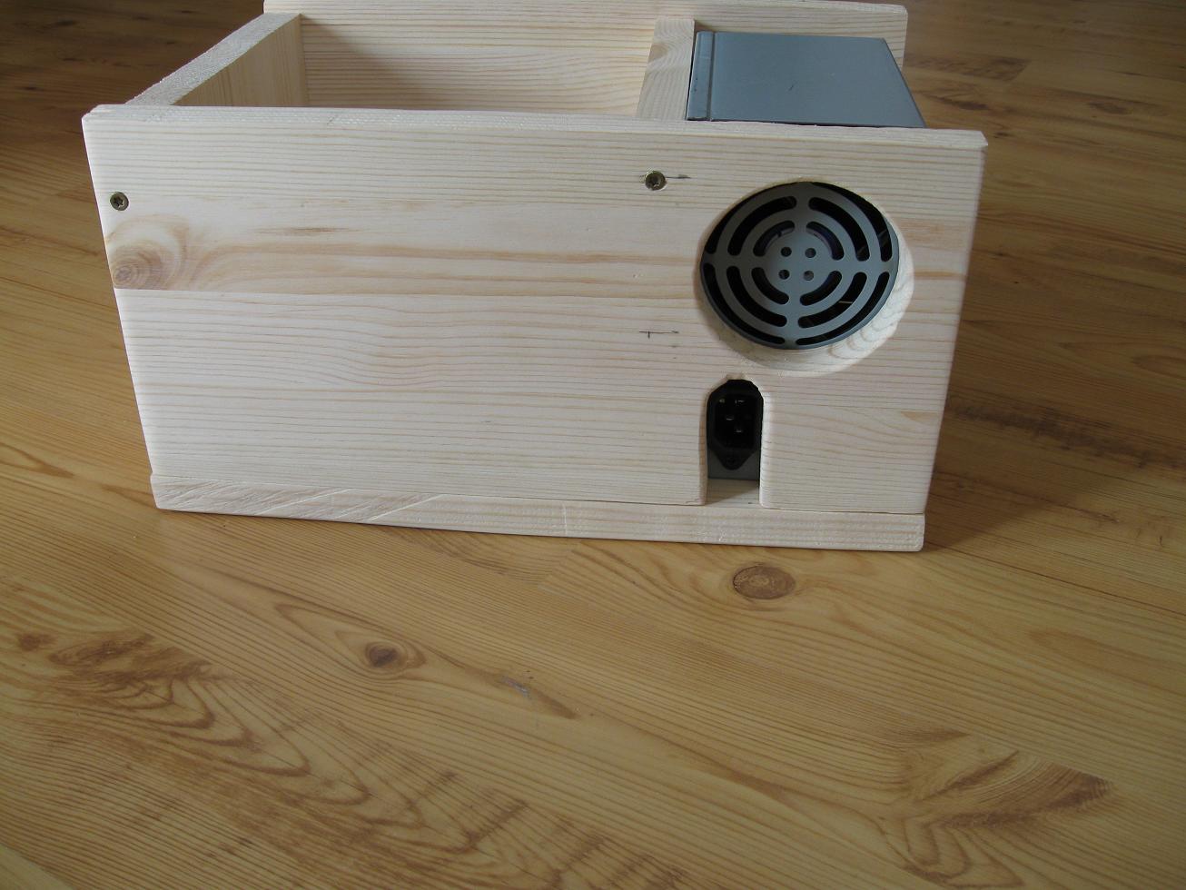
What next? Wood-working of course! I purchased some new pine sheets for
once, which look pretty good IMO. They smell nice too.
Now I bet you're wondering if my 30 EUR UV box can hold a match to the
550 EUR ones you can purchase from a supplier? It sure does, and I've
made a small guide on how I make
my PCBs in the "Misc" section. The
exposure time when using clear transparencies is just around 2 minutes.
The PCB can also be exposed through ordinary printer paper, for a
whopping 30 minutes or more. Unfortunately this wasn't expected, so the
timer only goes up to 9:59. I plan to fix up some new source code so
the timer can be adjusted to display just minutes as well as minutes :
seconds.
These projects originally set me on to this, so check them out too:
Disclaimer:
I do not take responsibility for any injury, death, hurt ego, or other
forms of personal damage which may result from recreating these
experiments. Projects are merely presented as a source of inspiration,
and should only be conducted by responsible individuals, or under the
supervision of responsible individuals. It is your own life, so proceed
at your own risk! All projects are for noncommercial use only.

 This work is licensed under a
Creative Commons Attribution-Noncommercial-Share Alike 3.0 Unported License.
This work is licensed under a
Creative Commons Attribution-Noncommercial-Share Alike 3.0 Unported License.