Before my Coolidge X-ray machine, I did my share of lesser x-ray
experiments in an attempt to find the most easily reproducible means
of creating an x-ray machine. The reason for this was the high cost and
rarity of x-ray tubes or heads, and the success of others using common
high voltage rectifier tubes. The idea behind these experiments is to
turn common vacuum tubes into x-ray emitters, by operating them well
outside of their normal operating conditions, in cold cathode mode. I
suggest you read my Coolidge X-ray machine article as well, as it contains some relevant information.
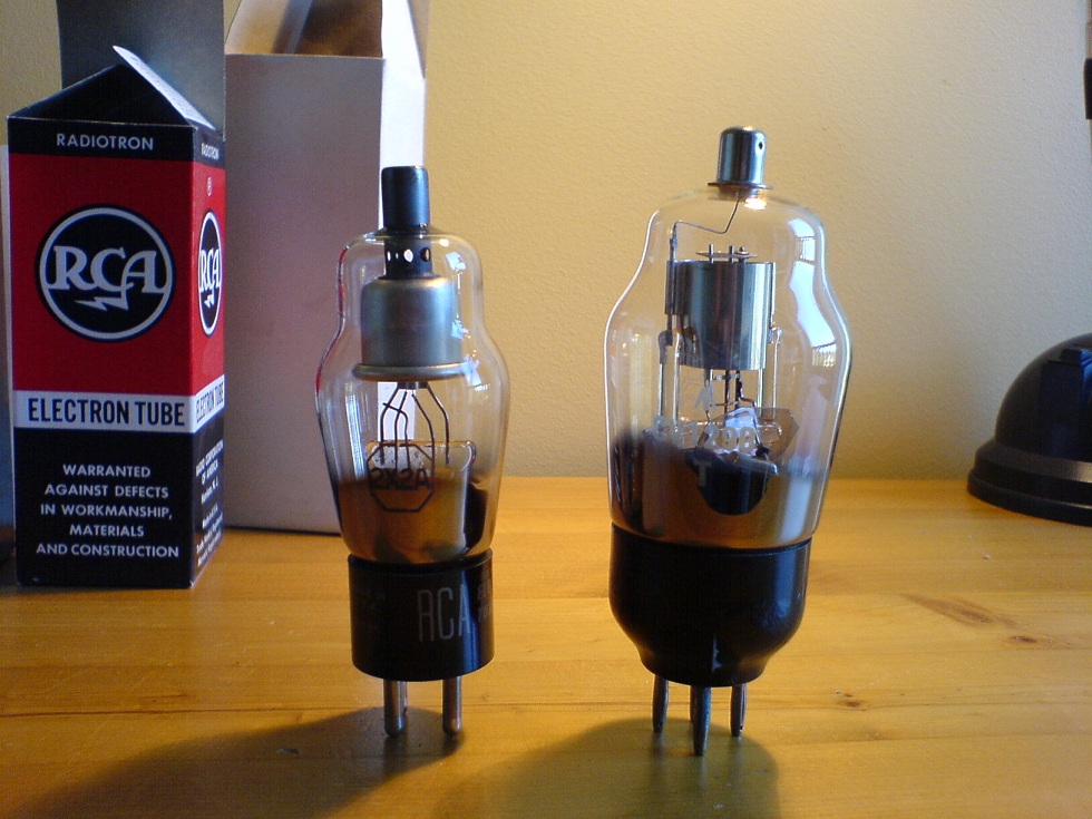
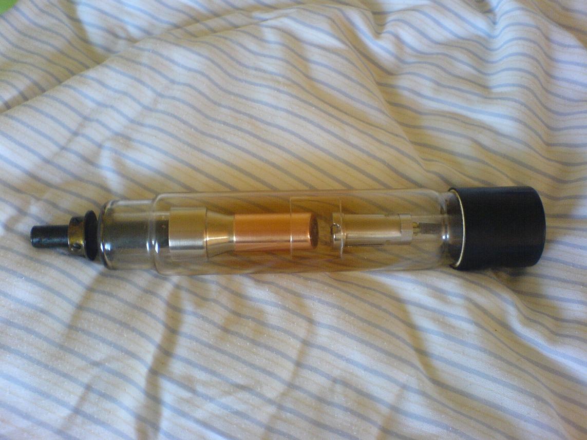
High voltage recifitier tubes. American 2X2-A on the left, and CV-1290 on the right.
SAFETY: Before you read any
further you should be aware of the
dangers
associated with conducting x-ray experiments. If your common sense
suggests that this is utter madness then you're predisposed for safety,
which
is good. Otherwise I'll need to scare you with some quick facts. X-rays
are ionizing radiation just like gamma rays, which means exposure WILL
cause damage to living tissue, which in effect increases your chances
of CANCER. Yes, the terrible disease you've heard so much
about.
Ionizing radiation can pass
through low density materials with the ease of light through glass, so
the only real protection is distance and thick, dense shields. As
though
X-rays aren't scary enough already, they can also reflect and scatter, sending
X-rays in completely new directions so a directional shield isn't
enough. Think of an X-ray tube as a lightbulb, if you can see the light
it emits, you're not entirely safe.
Early Marx Generator Experiments
Initially I tried to operate the rectifier tubes as a flash tube, by using a Marx generator as
the high voltage source. The benefit of this is low average current
through the tube, so heat dissipation doesn't become an issue, and
hence the
ability to largely choose operating voltage at your own desire. This is
contrary to DC operation, where the tube is run at a set DC voltage and
current which depends on the voltage and tube characteristics. The tubes
often behave as zener diodes, that is having a sharp increase in
current at some voltage. Since these tubes are only suitable for
a few tens of watts dissipation, the voltage you can run a tube at in
DC mode is quite limited. Another benefit is the relative simplicity of
constructing a Marx generator, as opposed to a DC power supply of
30-50kV.
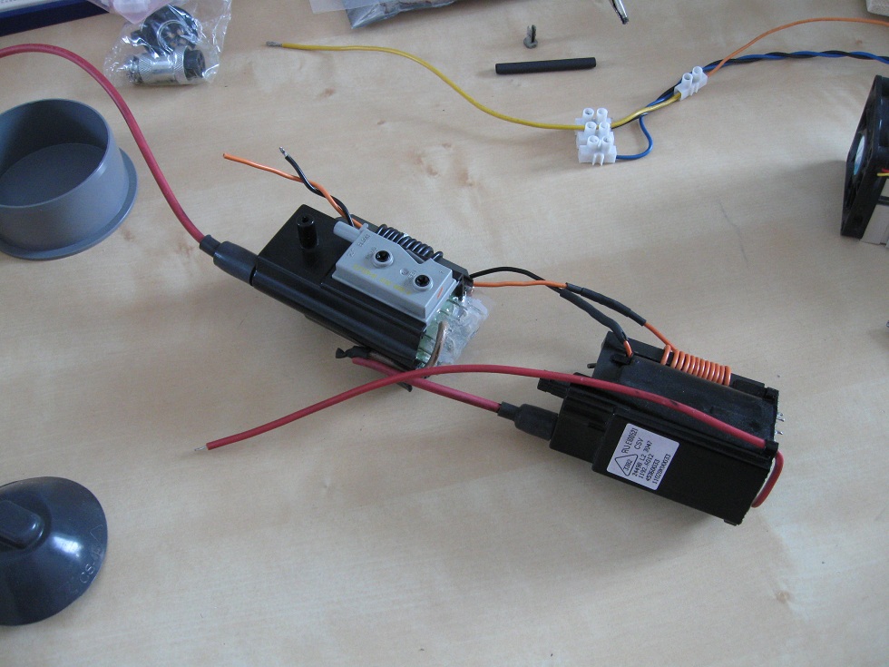
Marx generator and shielded 2X2-A rectifier.
The idea was to discharge
the 180kV Marx generator through a 2X2-A rectifier tube, thus causing a
massive burst of high energy x-rays. Leslie Wright
had great success doing this with other tubes, and his work was a
motivating force in these experiments. Unfortunately he has since
removed the all webpages regarding his technical x-ray work. The photo
above shows the x-ray setup I used, the rectifier tube itself is behind
a 30mm steel shield and submerged in oil to prevent arc-overs. Sadly,
this setup never proved capable of producing x-rays. Later I found this
was due to the small capacitors I had used in the Marx generator. Each
capacitor was a mere 470pF, meaning that the erected Marx capacitance
was 470pF / 20 stages = 23pF. This is roughly equivalent to the
capacitance presented by the load (rectifier tube under oil, feed
wires, etc) if not less. Therefor the voltage across the tube itself at
each firing would only be a fraction of the 180kV present without a
load. Later testing revealed that the tube conducts first at 40kV,
which explains why this setup was never able to produce x-rays. Had I
known this while experimenting, simply rebuilding the Marx generator
using 4.7nF or larger capacitors would probably have given results.
Flyback Transformer Driven Experiments
It wasn't until seeing a thread in the 4HV forum
that I became inspired to work on a rectifier tube x-ray machine
again. Radu had done some experimentation, and achieved incredible
results using very simple equipment. The entire thread is well worth
reading. He used the same model of rectifier I had and powered the
device using an AC flyback driven by a ZVS driver. This prompted me to
start working on a flyback stack which could provide 60kV (or so I
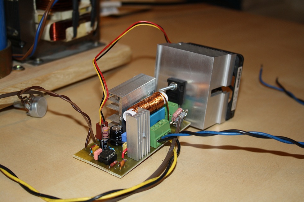
hoped). The driver used
was based on a current mode switch regulator, and designed by Jan
Martis. This driver regulates the mosfet/IGBT current, which means
overcurrent will never kill the switching device (high temperature
still can) and output power can be directly manipulated by turning a
single potentiometer. These two properties make this the ultimate
flyback driver.
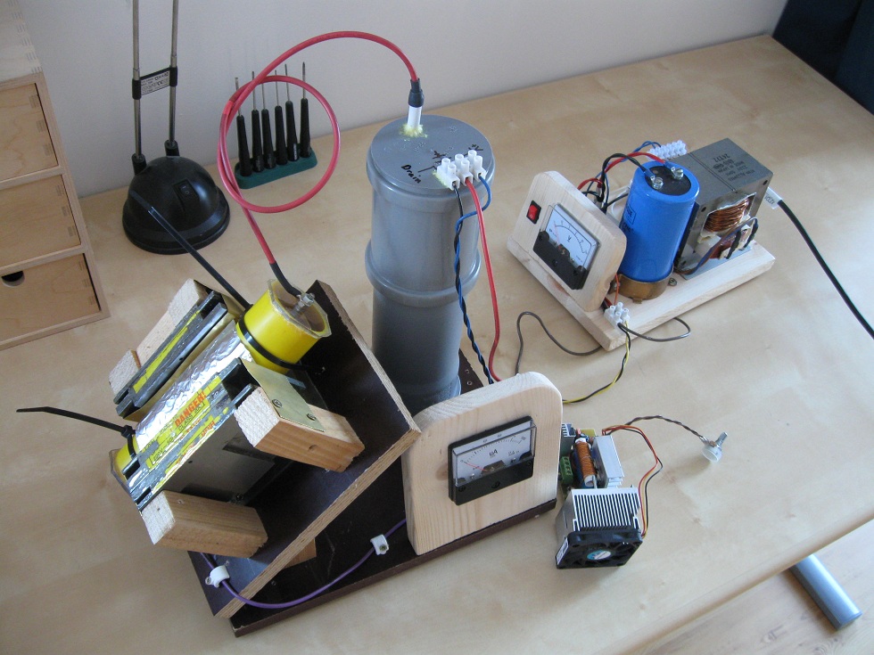
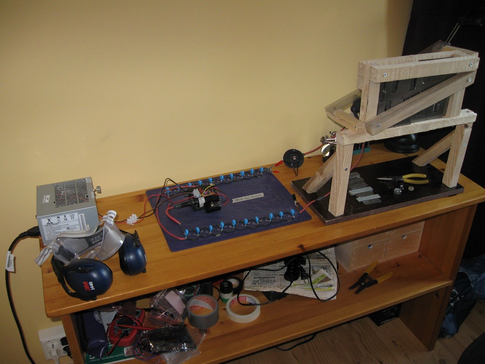
The two flyback transformers had their windings put in series,
secondaries and primaries respectively, then submerged in oil. To ease
experimentation, a rig was constructed which held a rudimentary
radiation shield, the oil submerged flybacks and a ammeter for
monitoring the current through the tube. In addition to this a timer
unit and relay were used to control exposures.
The vacuum tube can be operated in one of two modes, either with
correct or reverse polarization. In neither case is the filament
heated, at least not intentionally. As mentioned above the tube will
behave as a zener diode, and begin to conduct once a certain threshold
is reached which depends on the operating mode. Due to glass walls the
tube voltage should be above 20kV, otherwise very few of the x-rays
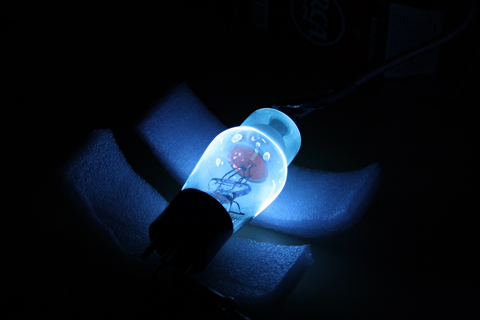
will penetrate the tube itself. Simply powering the tube without the
intention of x-ray production is entertaining in itself, as the
electron bombardment causes the glass walls of the vacuum tube to
fluoresce, and the internal structures to glow red with heat. Care
should
be taken though, as copious amounts of x-rays are produced if such a
light display is visible.
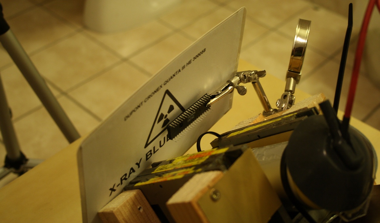
I was successful in taking x-rays using ths simple assembly, though no
where near the results Radu achieved. He had kindly sent some
fluorescent screens taken from dental image intensifiers, which I used
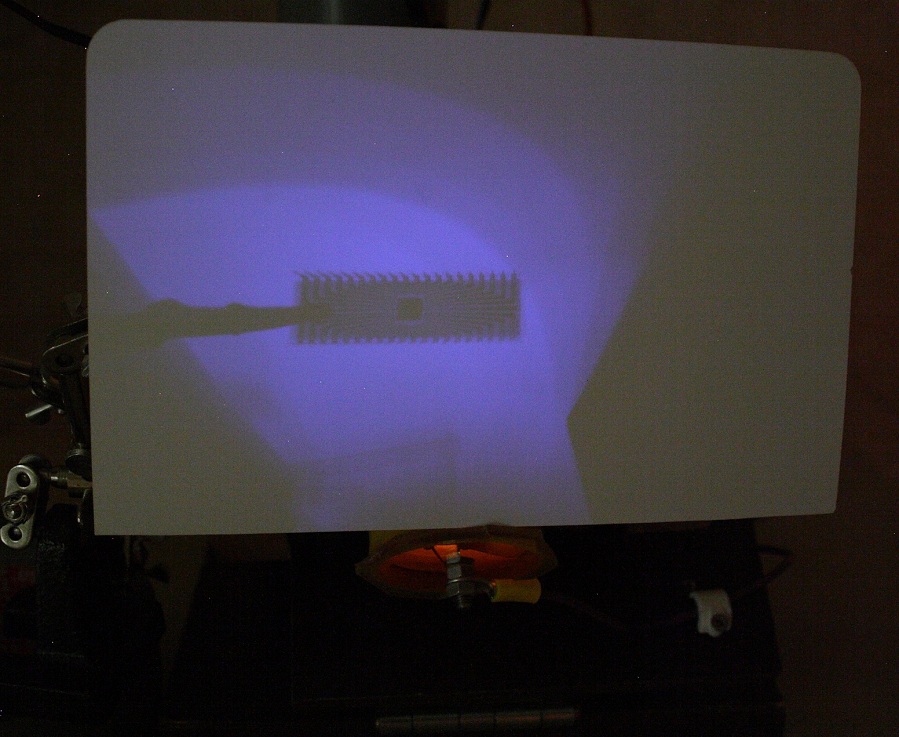
along with a DSLR camera to take some x-ray images. The photo below is
the best of the entire lot, requiring a 30 second exposure at a wide
aperture (3.5), and later digital enhancement. However, it proves the
concept is viable.
The x-ray above was taken with an American 2X2-A rectifier tube, at
44kV and 210µA. Due to the low voltage and current, only plastics can
be x-rayed as much denser materials provide too much attenuation.
Disclaimer:
I do not take responsibility for any injury, death, hurt ego, or other
forms of personal damage which may result from recreating these
experiments. Projects are merely presented as a source of inspiration,
and should only be conducted by responsible individuals, or under the
supervision of responsible individuals. It is your own life, so proceed
at your own risk! All projects are for noncommercial use only.

 This work is licensed under a
Creative Commons Attribution-Noncommercial-Share Alike 3.0 Unported License.
This work is licensed under a
Creative Commons Attribution-Noncommercial-Share Alike 3.0 Unported License.