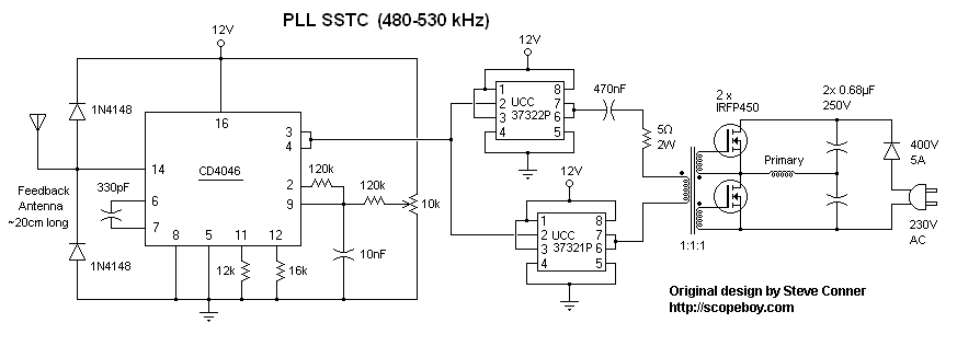
Streamers
with current
transformer feedback, half wave rectified.
I thought it was about time I made a SSTC. This is actually the product
of several weeks of trying different designs and secondaries. Instead
of going with a fail-proof concept first I tried various discrete
designs with little success, which I later see was most likely due to
the uber high fres secondary I was testing with. Anyway I decided I
just wanted it to work, so I made a low frequency secondary, and
settled on Steve
Conner's PLL. It has the advantage of easy startup thanks to
a constantly running oscillator, and with an antenna providing feedback
it's (nearly) always in tune. The best of both
worlds- in one chip.
The capacitor on pins 6
& 7 and the resistors on pin 11 and 12 determine the frequency
that the coil runs at. The ratio between R1 and 2 determine how far the
oscillator can wander. The 10k potentiometer by pin 9 will adjust the
voltage bias on the VCO input and alter the
frequency, or if running with feedback adjust the phase angle between
input and output. I suggest setting R1 and 2 for a 1.5 ratio during
testing, and reduce the ratio as you determine the exact resonance
frequency. This makes it much easier to tune for the perfect phase
angle. The best way to set up the 4046 is by setting the resistor range
first without the gate drivers, half-bridge or secondary. Basically
find some ballpark resistor and capacitor values, and then use the
potentiometer to see what frequency range you get. The 4046 is rated
for an operating frequency of up to 2.7 MHz,
so it'll work for practically any coil you may want to make. Audio
modulation is also possible by further biasing of the VCO voltage, but
I had to run my coil
from half-wave rectified mains to keep it from burning up, so it was
never implemented. Check Steve Conner's page
to see how. Once the circuit is
built the potentiometer must be used to tune for resonance.
The phase locking itself works by using an XOR gate to detect the phase
angle between the two inputs, pin 3 and 14. The output from the XOR
(pin 2) is a PWM signal, and the duty cycle will vary from 0 to 100% as
the phase difference between two 50% duty square waves moves from 0 to
180 degrees. A low pass filter is used to get a DC voltage proportional
to the PWM signal's duty cycle. This signal is fed into the VCO, which
then oscillates at some frequency set by the timing components R1, R2
and C1. (12k, 15k and 330pF in this case) A constant DC bias is also be
placed on the VCO input by the 10k potentiometer. Adjusting this bias
allows you to roughly set the phase angle.
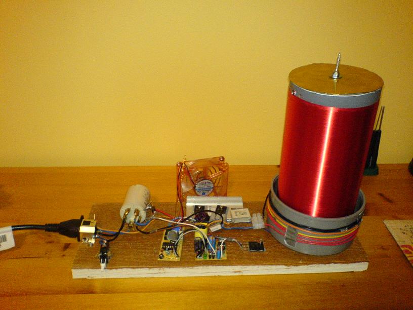
Mounted on a board for
quick and easy use.
SSTCs function much like SGTCs. A large secondary coil with much
inductance also has capacitance in the form of parasitic
capacitance between turns and capacitance from to the topload ground.
These reactive components form a resonant circuit, and if a
waveform is applied at the right frequency the AC impedance of the
setup is reduced to zero. By then coupling energy into this setup
through transformer
action we step-up the voltage by a ratio at the base, and this voltage
is stepped up further by the resonant rise. The result is an incredible
increase in
voltage. For a much more thorough explanation see Richie
Burnette's page on SSTC driving.
Coupling is important for getting power into the secondary
system, also explained in Richie's page. Quite simply put though, try
to get the coupling factor
as high as possible as this seems to work best for SSTCs. (K=1 implies
that the primary occupies the same space as the secondary, which is
impossible. High K means that the
primary coil is wrapped tightly and over as much of the secondary as
possible.) The limiting factor is
flashover, when sparks occur between the primary and secondary. Due to
insulating pipe size restrictions I was unable to tune for optimal
coupling, and thus the mosfets heat quite a bit. Ideally I would have
the primary reaching half-way up the secondary and with a few more
turns. This would reduce magnetizing current and couple more current
into the secondary.
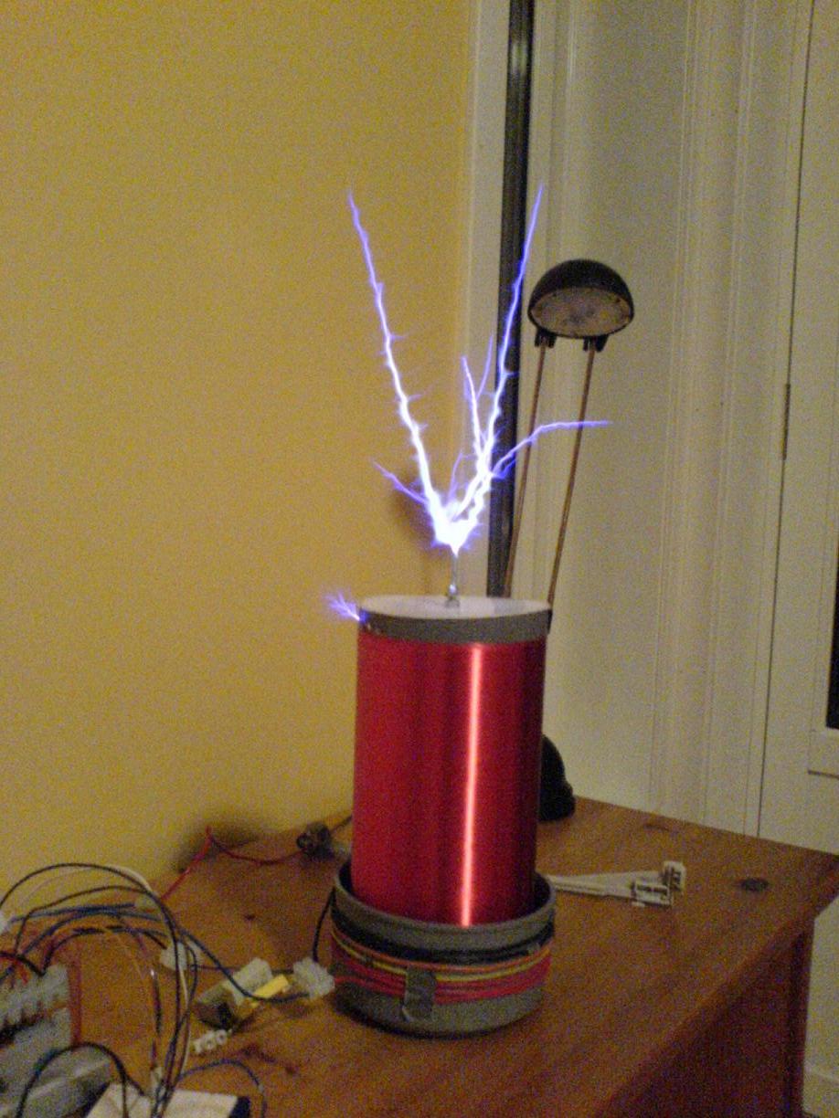
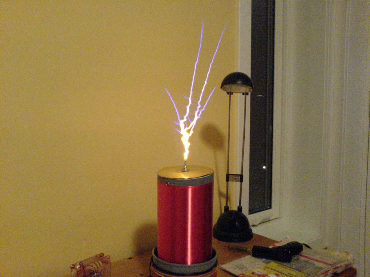
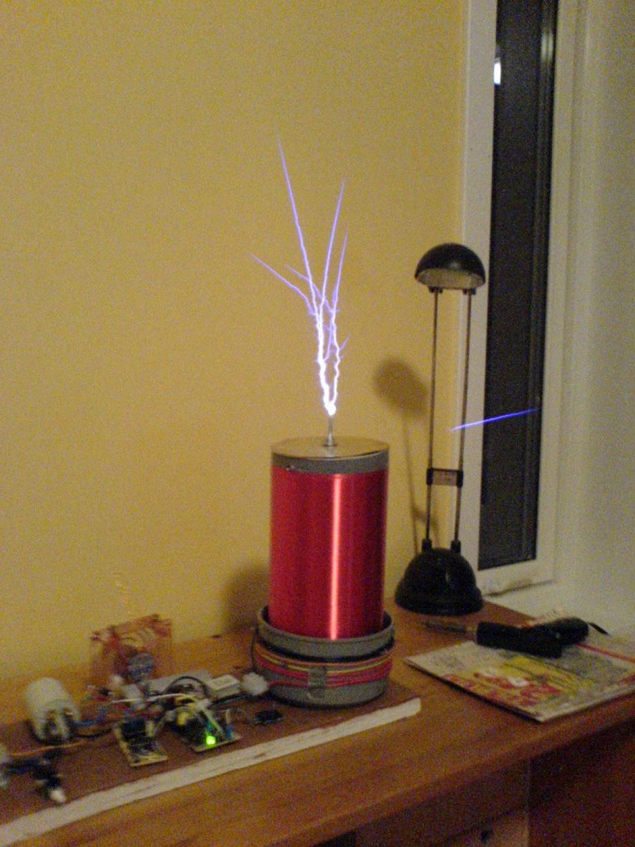
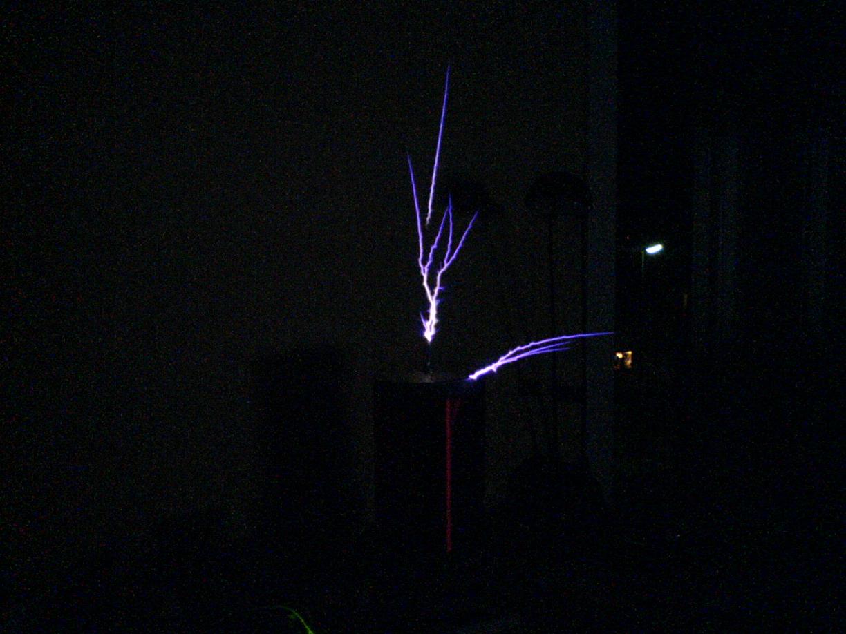
Left:
Nice thick streamers. This
was before I changed
the logic power supply to an auxiliary
smps
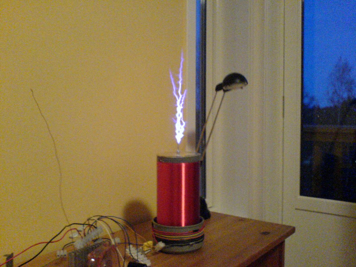
which altered the streamer appearance. The other
three picture show the result, much longer, but thinner streamers. The
pic on the top right shows how salt on the breakout point colors the
streamer. This works well with other salts too, just look up flametests
on wikipedia for other colors.
Disclaimer:
I do not take responsibility for any injury, death, hurt ego, or other
forms of personal damage which may result from recreating these
experiments. Projects are merely presented as a source of inspiration,
and should only be conducted by responsible individuals, or under the
supervision of responsible individuals. It is your own life, so proceed
at your own risk! All projects are for noncommercial use only.

 This work is licensed under a
Creative Commons Attribution-Noncommercial-Share Alike 3.0 Unported License.
This work is licensed under a
Creative Commons Attribution-Noncommercial-Share Alike 3.0 Unported License.