In many of my projects I find the need for a small logic power supply
to finalize the project. Wall warts would work fine if I had a bunch of
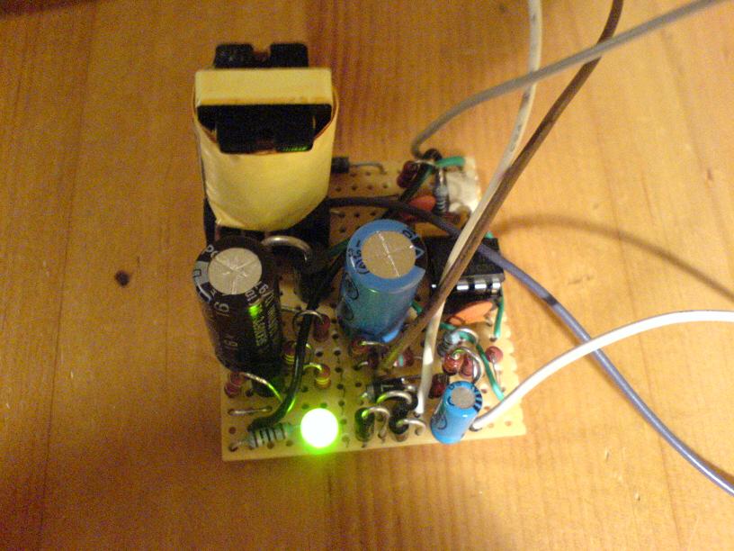
them. What I do have are lots of useless ferrite transformers from junk
I've gutted. Since ferrite requires high frequencies to avoid
saturation, a special driver is needed. Since most of these
transformers were driven in flyback mode, and it
only requires one switching device, flyback topology is the natural
choice. There are various discrete versions out there, but using a
specialized IC eases troubleshooting and makes it more
universal. The
only real difficulty is setting up the auxiliary voltage for the UC3842
itself, and working out the transformer phasing. After much testing
with different transformers I finally found the auxiliary flyback
transformer from an ATX supply to work well. Since almost all ATX
supplies are equivalent, any aux transformer from any ATX supply should
work with this smps.
For the mosfet anything with a rating of
450V or more can be used. I used an IRFP450, which is complete
overkill. Small mosfets with low current ratings will work fine, as the
primary current is limited to about 0.5A. Large on resistances are no
problem at such low currents, so dig out your trash fets and put them
to use! The circuit starts with 320V being dropped across the 150k
resistor and into the 10µF cap. Once it has charged to 16V
the UC3842 fires up, and pulses the primary through the mosfet. This
pulse of energy is sent to the output and rises the voltage, and at the
same time to the AUX winding. After the UC3842 has fired once, the
10µF cap would take some time to recharge with just the 150k
resistor. The UC3842 has an under-voltage lockout function, which turns
it off once the voltage sinks below 12V. The voltage must then rise
above 16V to turn the UC3842 on again. However the power from the AUX
winding puts more power into the 10µF cap, keeping the voltage
above 16V, and clamped to 18V by the zener. When a load is applied to
the secondary the aux voltage will rise to dangerous levels, which is
the reason for the zener and limiting resistor. The TL431 is a
programmable
reference detector, and can be set to turn on the optocoupler at the
desired voltage. Once on, the optocoupler produces a signal at VFB,
keeping the voltage regulated. If no VFB is present, the power is
limited only by the current sense resistor (2.2 ohms) to 0.5A. The
circuit is very customizable, and voltages between 1 - 20V are easily
obtainable. Power will tend to stick around 15W with small
transformers. See the UC3842 datasheet for more info regarding design.
A common problem I had with this supply was failing output. The voltage
was right, but would drop immediately with load, and clicking noises
could be heard from transformer. This was caused by the auxiliary supply
not working, and can be easily confirmed by using an external supply to provide power to the UC3842.
Reversing phasings of the winding would usually solve this, if not a
different transformer is required or a different output voltage.
(remember the aux voltage varies with secondary voltage.)
Disclaimer:
I do not take responsibility for any injury, death, hurt ego, or other
forms of personal damage which may result from recreating these
experiments. Projects are merely presented as a source of inspiration,
and should only be conducted by responsible individuals, or under the
supervision of responsible individuals. It is your own life, so proceed
at your own risk! All projects are for noncommercial use only.

 This work is licensed under a
Creative Commons Attribution-Noncommercial-Share Alike 3.0 Unported License.
This work is licensed under a
Creative Commons Attribution-Noncommercial-Share Alike 3.0 Unported License.