GDT's or "gate drive transformers" are used in numerous circuits as a
simple level-shifter/galvanic isolator/signal inverter for
half/fullbridge drivers. You
may have noticed one in my Multipurpose inverter, PLL SSTC or PLL
Induction heater. They have a number of advantages, such as providing
isolation between the drive and power circuitry, introducing very
little extra
delay and being simple to construct. I've built many GDT's and to begin
with they seldom
worked correctly. Things such as leakage inductance, minimum number of
primary turns, core material were beyond me. I would
simply wind an arbitrary number of turns on a tiny EE-core and hope for
the best. As I've gained experience in the matter I've learned that the
little details such as core material, and how one winds the turns are
very important for creating a functional GDT.
First
off, you need a
proper core. The core must be ferrite, and have
as small an air gap as possible. Perfectly suited for this are toroidal
cores. Toroids can often be found as filters on various signal or
ground cables in monitors or other equipment. Unfortuanetly, these
toroids are sometimes powdered iron, which is unsuitable, making it a
bit
of a lottery. Powdered iron cores are generally color coded, and most
often with two different colors. Ferrites on the other hand tend to be
a single color, or unpainted. The core to left is a suitable ferrite
for example. When shopping for a core look for one with a high high
permeability or "AL" value, as this means more inductance per turn and
less magnetizing current. Once you have a core you need to know how
many primary
turns are
required. This depends on the drive voltage, frequency, the core's
cross sectional area and the maximun flux density the core can handle
at a given frequency. Fortunately these are
related by a simple formula:
N
= ( V x t ) / ( B x Ae
)
Where N is the minimun number of primary turns, V is the voltage
applied to the core, t is the time the votlage is applied, B
is
the peak flux density and Ae is the cross sectional area of the core.
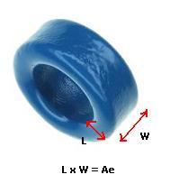
The core's cross sectional area, Ae, is the core area within
single turn on the toroid. It can be found by measuring the length and
width of
the core where you wish to wind, or in the core's datasheet.
The maximun flux density
you want in your core can range from 0.1 – 0.3 Tesla for
depending on the drive frequency. As frequency increases the core will
heat more unless the flux density is decreased. For 100 - 200kHz, 0,25T
works fine in most cases. The core datasheet will specify the flux
density at various frequencies if you don't feel like experimenting.
I've made a spreadsheet for quick
GDT design, which can be downloaded >HERE<.
How you wind the turns are an equally important part of GDT creation as
the
other stages. With the wrong winding technique the leakage inductance
(which is like an inductor in series with the load) will be large
enough to resonate with the gate. This would cause a messy drive
signal, which could be bad enough to put the mosfet into the linear
range or even switch it at a higher frequency than intended. James
Pawson from "thedatastream" collected some experimental
data on different
winding techniques to see how they alter the amount of leakage
inductance. From the data it was determined that using screened wire
(coaxial cable such as in headphone cable) or the poor-mans alternative
trifilar-wound wire (Trifilar-wound wire is 3 strands of wire
twisted together first, then wound as a single winding) resulted in the
least leakage inductance. The wire should also be wound over as much of
the core window as possible.
This information has been gathered from the following sites which I
recommend you read. My “guide” is a mere summary
for the
impatient type, a starting point for someone clueless on the subject,
there's a whole art behind making proper GDTs!
Disclaimer:
I do not take responsibility for any injury, death, hurt ego, or other
forms of personal damage which may result from recreating these
experiments. Projects are merely presented as a source of inspiration,
and should only be conducted by responsible individuals, or under the
supervision of responsible individuals. It is your own life, so proceed
at your own risk! All projects are for noncommercial use only.


 First
off, you need a
proper core. The core must be ferrite, and have
as small an air gap as possible. Perfectly suited for this are toroidal
cores. Toroids can often be found as filters on various signal or
ground cables in monitors or other equipment. Unfortuanetly, these
toroids are sometimes powdered iron, which is unsuitable, making it a
bit
of a lottery. Powdered iron cores are generally color coded, and most
often with two different colors. Ferrites on the other hand tend to be
a single color, or unpainted. The core to left is a suitable ferrite
for example. When shopping for a core look for one with a high high
permeability or "AL" value, as this means more inductance per turn and
less magnetizing current. Once you have a core you need to know how
many primary
turns are
required. This depends on the drive voltage, frequency, the core's
cross sectional area and the maximun flux density the core can handle
at a given frequency. Fortunately these are
related by a simple formula:
First
off, you need a
proper core. The core must be ferrite, and have
as small an air gap as possible. Perfectly suited for this are toroidal
cores. Toroids can often be found as filters on various signal or
ground cables in monitors or other equipment. Unfortuanetly, these
toroids are sometimes powdered iron, which is unsuitable, making it a
bit
of a lottery. Powdered iron cores are generally color coded, and most
often with two different colors. Ferrites on the other hand tend to be
a single color, or unpainted. The core to left is a suitable ferrite
for example. When shopping for a core look for one with a high high
permeability or "AL" value, as this means more inductance per turn and
less magnetizing current. Once you have a core you need to know how
many primary
turns are
required. This depends on the drive voltage, frequency, the core's
cross sectional area and the maximun flux density the core can handle
at a given frequency. Fortunately these are
related by a simple formula: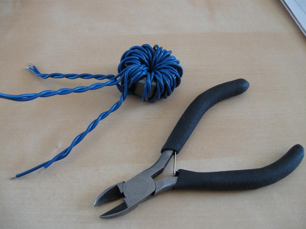
 This work is licensed under a
Creative Commons Attribution-Noncommercial-Share Alike 3.0 Unported License.
This work is licensed under a
Creative Commons Attribution-Noncommercial-Share Alike 3.0 Unported License.