It was recently brought to my attention by Kilian Brixel that there is a bug in this code, where a note off status byte would
be ignored if the velocity was not also set to zero. I've corrected the mistake, and uploaded new projects for Atmel Studio. They can
be downloaded here. TeslaCoilMidiInterrupterFirmware_fix17.07.2017.zip
If you are compiling this with GCC, then the UMSEL0 needs to be renamed to UMSEL.
09.12.09
The Polyphonic Tesla Coil MIDI Interrupter, quite a mouth-full isn't
it? This device is basically a modular MIDI
player, which can be used as a Tesla coil interrupter or synthesizer.
For those who aren't familiar with MIDI, it's a music standard used
largely by keyboards and drum pads, in which simple commands are sent
serially, such as note on and off information and intensity, but not
actual music. That job is left to the synthesizer, which is simply told
when a note is on or off, and must create the corresponding sounds
(frequency, waveform, etc) itself in order to make audible music. So no
matter what the original song is supposed to sound like, the MIDI
signals simply tell us when a key is on or off (and a lot of other
information, but nothing that's interesting for this project). This is
perfect for Tesla coil modulation, as every SSTC or DRSSTC can be
interrupted, and by interrupting the coil at the same frequency as the
note being played, we can create music!
This project has evolved from a monophonic MIDI player using a single
ATmega32, to a multi-channel, multi-note (polyphonic) MIDI player using
cascaded ATtiny2313s. Each ATtiny2313 can play two notes at once, using
Timer1 and the two Compare Match modules. The AVRs are organized so
they all receive the same input, but only start playing notes once an
enable input (PD5) is set high. Once an AVR has used both it's compare
match modules to play notes, ie is full, an output pin (PB0) goes high.
This way they can cooperate, and in theory play and infinite number of
notes at once. The MIDI channel that the AVRs listen on is set using
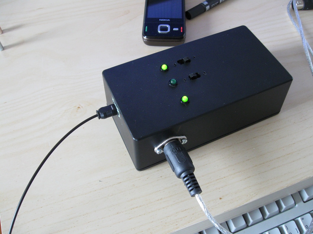
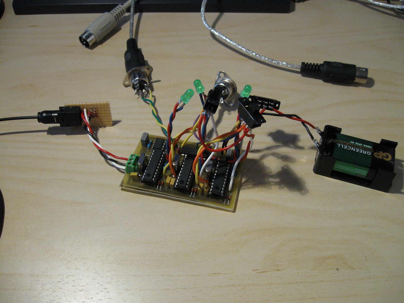
the four most significant bits on PORTB. I've made a small example
circuit where three ATtiny2313s are chained together, and can either
play 6 notes on one channel, 4 notes on channel 1 and two on channel 3,
or two notes on channels 1,2 and 3. All depending on
the position of two switches. The firmware was made using
WinAVR (AVR-GCC). Firmware, schematic, a command-line program for
determining the compare match values AND PCB files (w00t!) can be found
here. -> TC
MIDI Interrupter.zip
For anyone else who wishes to tread down the path of MIDI and AVRs, I
recommend you read this
article by Paul Maddox. It was a
reference I used throughout the entire process, and saved me a lot of
headaches. (not to say I still didn't encounter enough of them.) Also,
if you wish to mix several notes together you need to keep the duty
cycle low (~5%). This is obvious once it's been pointed out (thanks
Steve Ward), because you can only send one bit of data down the line,
and mixing two square waves results in areas at V/2 - which would
require 2 bits of data to describe. Keeping the duty cycle low reduces
the chance of an overlap. And the more square waves you mix the more
bits are required. It's easy to see graphically if my explanation is
poor.
The firmware itself is interrupt-driven. MIDI bytes are processed as
soon as they are received, and once a full MIDI packet has been
received a note is either turned on or off. When a note is turned on
the correct off-time and on-time values are looked up and stored for
quick access, and interrupts are enabled for one of the compare
modules. If both compare modules are now busy an output pin is set high
to alert any other AVRs in the chain that it's full. Once a compare
module generates an interrupt, an output pin is toggled and the time
until the next interrupt is determined depending on whether it's in a
high or low state (to get an asymmetric waveform (less than 50% duty
cycle)). When a note off event occurs the AVR first checks that it's
actually playing the note before stopping one of the compare modules.
The main program loop is used to indicate when notes are being
played, to check what channel to listen on and to enable or disable the next AVR in the cascade.
So far I've tested this interrupter on two Tesla coils, see the links
below. You can also check out my youtube channel, where I have some
more videos uploaded.
Energy Labs used this design to create a PIC based version, for those more inclined to Microchip.
Project link.
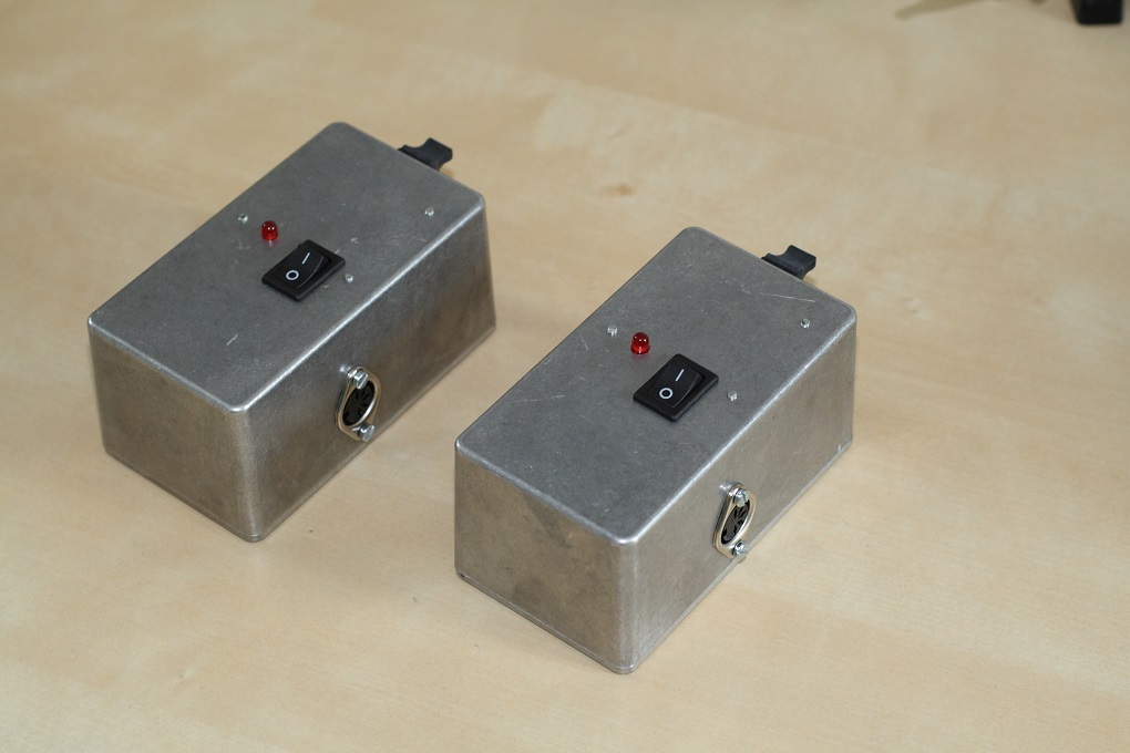
DRSSTC edition!
Update 10th July 2013
I've recently built a DRSSTC, and in order to use the MIDI interrupter with
it I had to make some alterations. Most importantly, the maximum
on-time had to be limited (this applies to low frequency notes) and the
range of frequencies had to be truncated. My DRSSTC would only respond
to notes below middle C, anything else would simply result in no
output. I suspect this is the case with most DRSSTCs, due to the time
it takes the tank current to ring up. To counter this, I had the MIDI
interrupter shift all received notes down one octave, and at the same
time ignore notes above a defined key. The duty cycle in the provided
firmware was set to 1,88%, or 3,75% with both notes playing at once,
and with the maximum on-time limited to 250us per note.
The compare notes generator was
rewritten in Golang, which is Google's "spiritual successor" to C.
A version of the code is provided which will run directly on the Golang
site's servers, so no installation is even needed. What this code does
is automatically generate the correct timer values needed in the
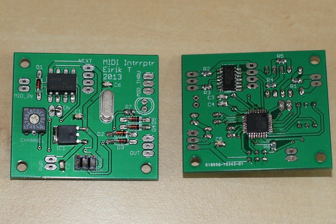
firmware, if you wish to alter the duty cycle or on-time limit. A new
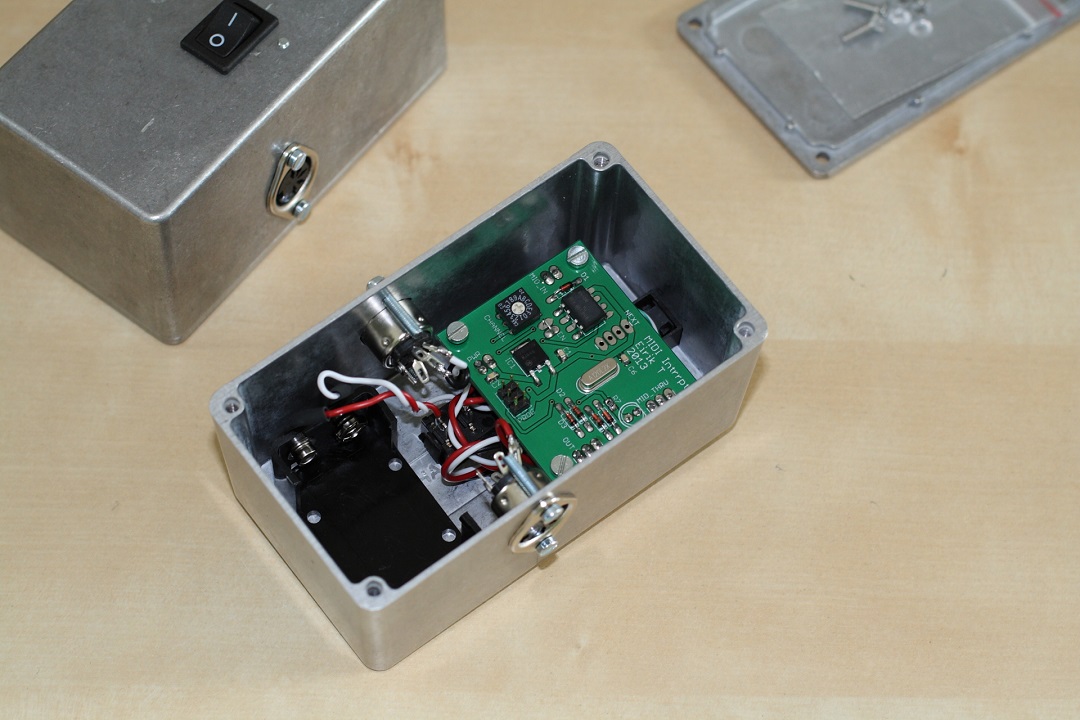
circuit layout and microcontroller is used, which I have made a PCB
layout for. All required design files can be found here.
Like the version above, the layout here assumes you will be using your
own TLL compatible fiber optic unit, or any other Tesla coil interface
of your choosing.
Disclaimer:
I do not take responsibility for any injury, death, hurt ego, or other
forms of personal damage which may result from recreating these
experiments. Projects are merely presented as a source of inspiration,
and should only be conducted by responsible individuals, or under the
supervision of responsible individuals. It is your own life, so proceed
at your own risk! All projects are for noncommercial use only.

 This work is licensed under a
Creative Commons Attribution-Noncommercial-Share Alike 3.0 Unported License.
This work is licensed under a
Creative Commons Attribution-Noncommercial-Share Alike 3.0 Unported License.