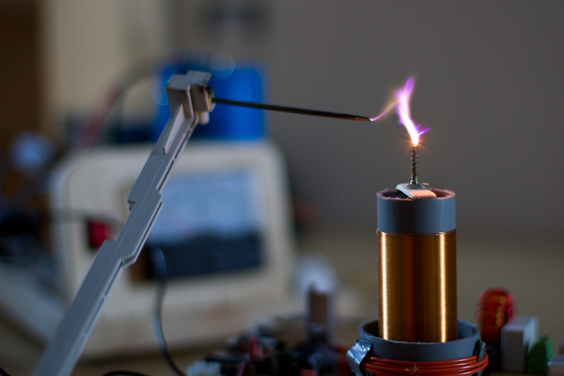
Wanting to take the step up from my Palmtop SSTC I decided to do a
proper, class E, 4MHz SSTC. For those who have never seen these before,
the basic idea is to use a switching topology commonly used in RF
amplifiers, instead of the usual half or fullbridge. The reason for
this is too greatly reduce switching losses in the power mosfets.
Richie Burnett was the first to use this topology in a Tesla coil, and
since then many have built similar coils.
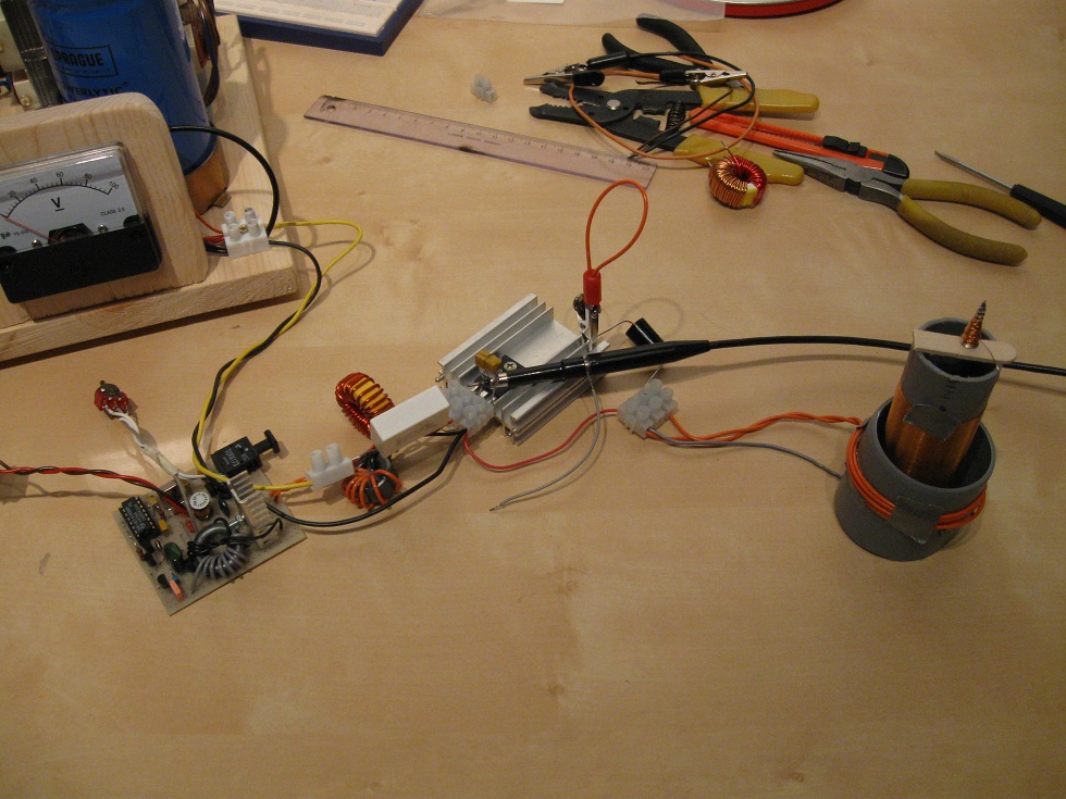
The driver used for the 4MHz class E SSTC is a string of several
amplifiers, which buff up the signal from a 4.096MHz crystal. It's
pretty straightforward until the first mosfet stage, where the high
frequency fun begins. The IRF630 gate is driven through a small
transformer, which is biased at around 3V. The bias reduces the amount
of voltage swing required to reach for gate potential, and the
transformer helps match the 2N390X stage to the gate impedance. Leakage
inductance in this transformer also play a part, by creating a resonant
circuit along with the gate capacitace. If tuned properly a nice sine
wave can be created on the IRF630 gate, allowing for proper gate drive.
Which is all well and good, but there are still two stages left to
tune! The next stage is actually a class E stage which is used just to
drive the IRFP450 gate. Again the gate transformer must be carefully
tuned for the best waveform, but in addition you want to tune for a
class E waveform on the IRF630 drain. (See below for how to tune class E)
To be honest here, I had already tuned the IRF630 when I discovered
moving the windings on the gate transformer had a profound effect on
the waveform amplitude. At this point I simply moved the windings until
the IRFP450 received a perfect sine-wave gate waveform, and simply let
the IRF630 drain waveform be. If overall system losses are a major
concern, you'll need to put more effort into tuning the IRF630 than I
did! One fun thing to note, is that at this stage we're already
generating roughly 5W of RF power just in gate drive. Without a
heatsink your IRFP450 could overheat just from gatedrive alone, given
time.
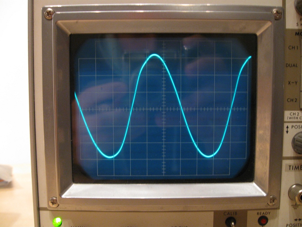
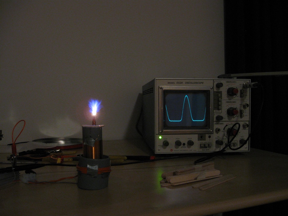
IFRP450 gate, 5V div, 40ns
Once the IRFP450 gate waveform is perfected, you're only about halfway. The
final class E stage is the one that counts, and tuning it can be
tricky. At this frequency minor changes of the secondary or even
primary can destroy the tuning. I experienced this myself, as I had
originally tuned everything to working order, and then foolishly
decided to cut off any remaining PVC from the formers to get a more
deliberate look to the project. Little did I know that the 1cm of PVC
removed from the secondary and primary formers were adding vital
amounts of capacitance to the setup! I was forced to make a new
secondary, so make sure you don't repeat my mistake! In essence you'll
need to use a more or less set value of drain capacitance, and tune the
primary and secondary until you get both breakout, and a good class E
waveform. This process takes time, so be prepared to do some
experimenting.
Tuning for Class E
As mentioned earlier the premise for class E is to reduce switching
losses. This is achieved by turning on the switch with zero current and
zero voltage across it.
Despite having tuned my coil, I still don't have a good procedure for this. When you tune or adjust one
component, everything else that was previously optimized needs
readjusting. For this reason you'll need to tune and retune many times
before arriving at an optimal tuning. For starters wind a coil with a
resonant frequency somewhat below your target frequency. This will allow you to
remove turns later. Then estimate the values (or use the ones in the
schematic) of the class E components, and power it up while watching
the drain waveform. If it appears as a half-sine wave that is cut off
before reaching zero, you need to remove some turns from the secondary.
If it appears as a sharp spike, at less than 50% duty cycle, you need
to add some turns to the secondary. Once correct, you should have
breakout when run from 50V.
Now you'll need to tune the primary side. You'll need to experiment with
both coupling and inductance, and possibly the drain-source capacitance
and RF choke. Decent values of the RF choke and drain source cap can be
found even if your setup isn't tuned perfectly, so start here. Once
you've settled on values for these components, you need to experiment
with the primary winding. Some of the factors that come into play are:
Disclaimer:
I do not take responsibility for any injury, death, hurt ego, or other
forms of personal damage which may result from recreating these
experiments. Projects are merely presented as a source of inspiration,
and should only be conducted by responsible individuals, or under the
supervision of responsible individuals. It is your own life, so proceed
at your own risk! All projects are for noncommercial use only.

 This work is licensed under a
Creative Commons Attribution-Noncommercial-Share Alike 3.0 Unported License.
This work is licensed under a
Creative Commons Attribution-Noncommercial-Share Alike 3.0 Unported License.