Receiving Weather Satellite Transmissions with an RTL-SDR
09.01.2017
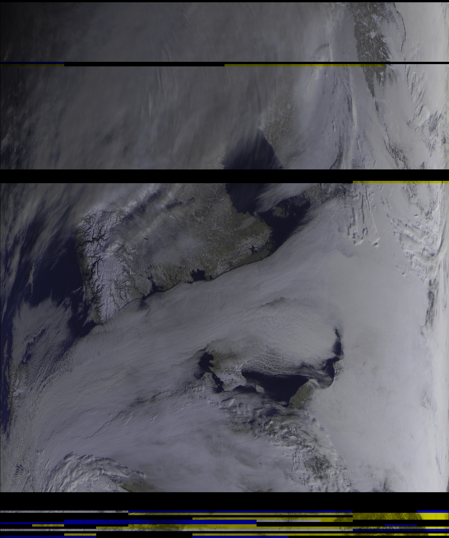
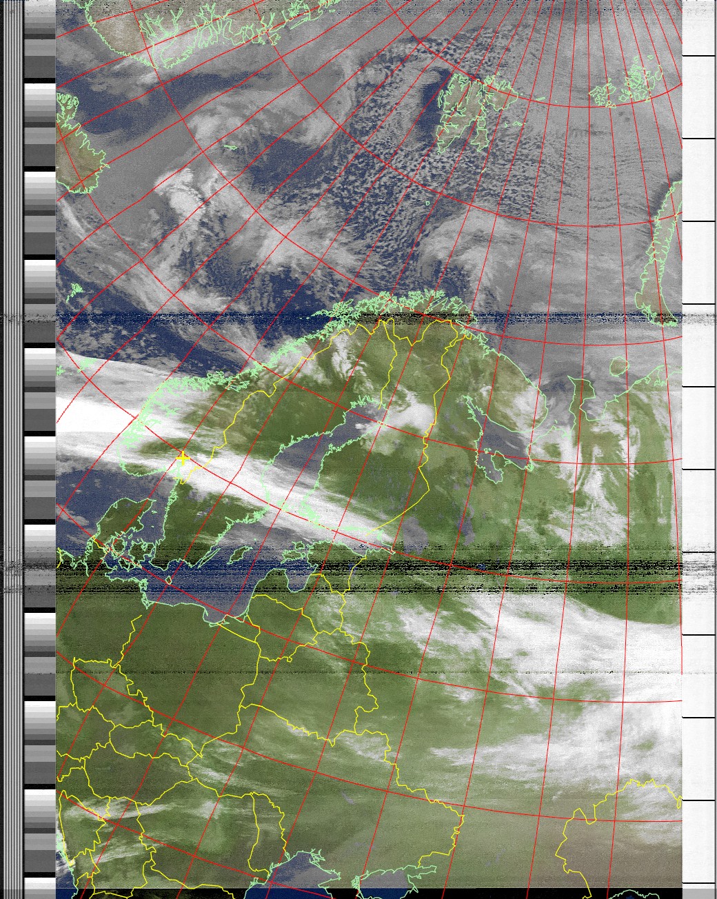
Received satellite images
Upon receiving my RTL-SDR, I immediately began scanning local frequencies, and seeing what I could eavesdrop on. Besides the novelty of finally being able to see how an FM bug I made years ago looks amongst all the local radio stations, and trying to identify strong transmissions near me, I quickly ran out of things to do. In the end, an SDR is a tool, and the real fun is using it for a specific purpose. So I left it in a box for a long time (years?) until I saw some articles on the net where people had used their units to receive real-time weather satellite transmissions! Now THAT, caught my interest. After some research I learned that this is something hams have been doing for some years, so there is plenty of information on the net, and even more helpful, a lot of good software. The main hardware investment was going to be a good antenna.
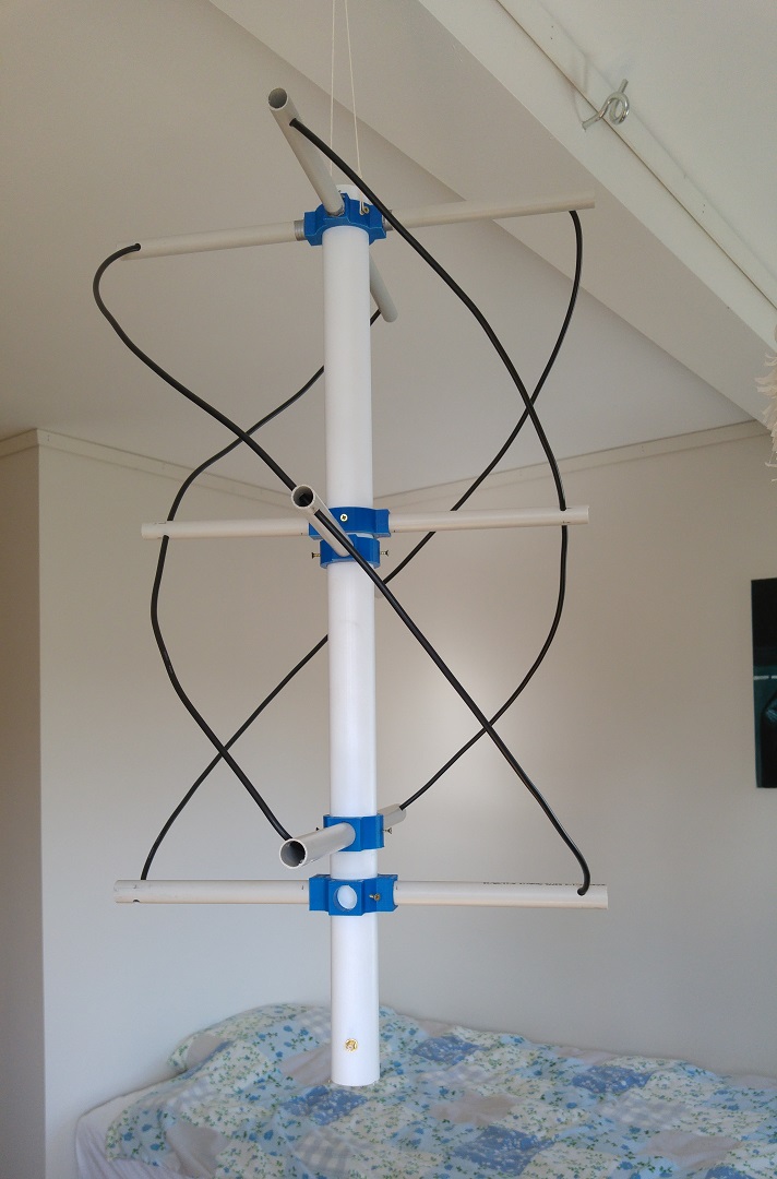
Quadrifilar Helix Antenna, for 137MHz
The main two types of antenna used are the turnstile, and the Quadrifilar Helix Antenna (QFH) antenna. Based on the opinions of those who have tried both, I opted for the QFH. In my opinion it seems more mechanically elegant, and easier to construct correctly, though this doesn't impact reception at all. The QFH is an omnidirectional, circularly polarized antenna (see below). It consists of two loops, which are run 90 degrees out of phase in order to produce circular polarization. A common choice is to use thick coaxial cable to construct the antenna, as it is easy to work with and cheap. The only disadvantage to this is marginal reduction in the antenna Q factor. I'll refer you to this website right away as it contains all the information you need, along with a calculator. And this page which describes the connections, and how impedance is matched.
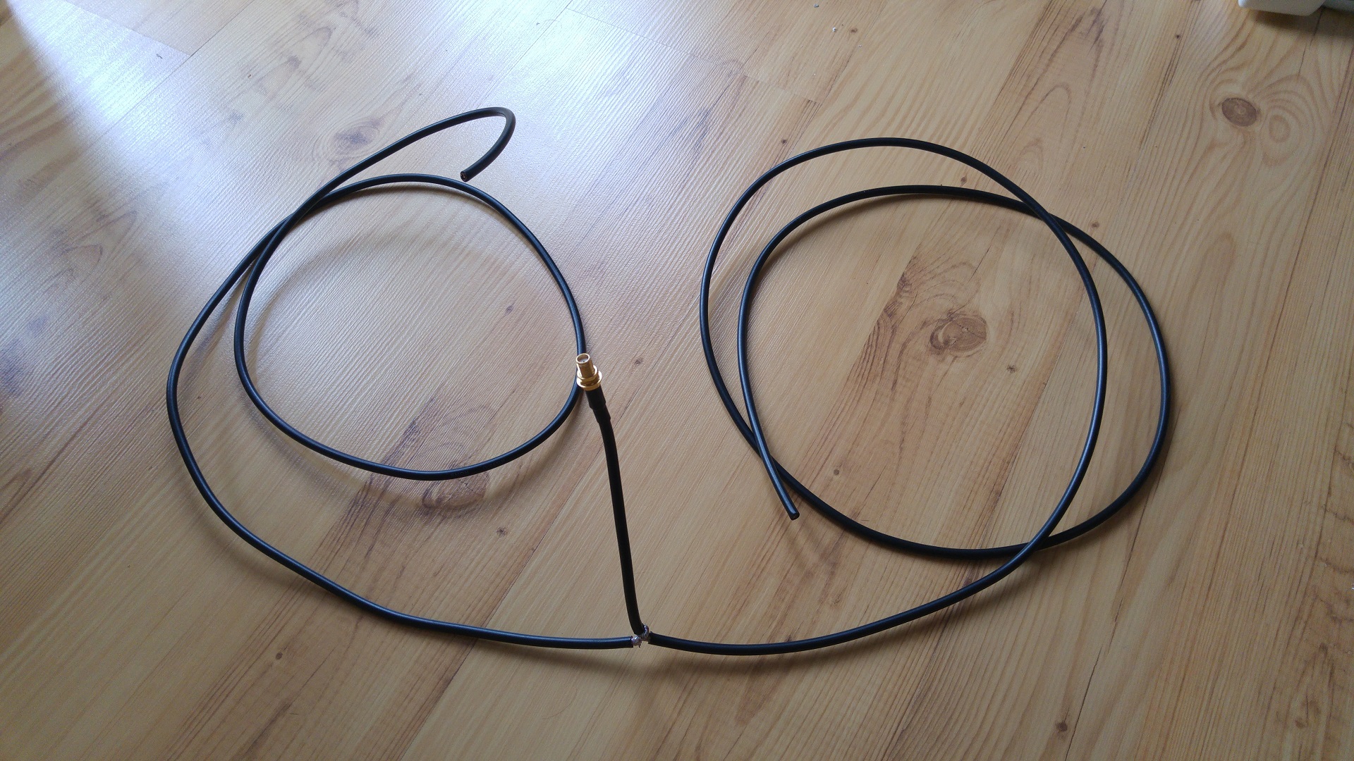
Construction of the QFH antenna can be tricky to comprehend without seeing one, as the coaxial cables need to be connected at the right places, in the correct manner. I spent some time trying to figure out just how it was supposed to work, before it finally clicked. What you have are two loops, one smaller than the other. I'll use some numbers for a 138MHz antenna, with 5mm diameter coax. Punch this into the above calculator to see for yourself. When actually constructing the antenna, make sure to use a little extra coax, so you can tune it later.
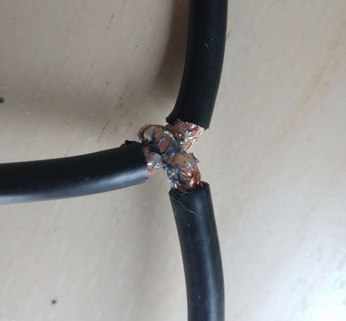
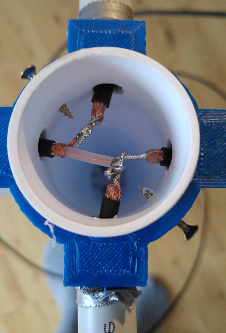
Now, the smaller inner loop is made of one length of coaxial cable, in which you solder the center lead and shield together at both ends. The cable should 2276mm. Basically you just want a single length of conductor for the smaller loop. The larger loop is split in two. One length is equal to half of the total length given in the above calculator (2395 / 2 = 1198mm), and it also has core and shield solder together on both ends. The other length equal to half of the total length PLUS whatever you want as a connector for the antenna (1198mm + e.g. 300mm = 1498mm). Both ends of this cable are left OPEN! You should now have three pieces of coax. One which is the total length of the smaller loop (2276mm), one which is half the length of the larger loop (1198mm), and one which is a little longer than half the length of the larger loop (1498mm). What you do now is remove the shielding at the 1198mm mark for the 1498mm long coax cable. Then you solder the other 1198mm long cable to this location, resulting in a coaxial cable with a stub connected to it's shield. See the image below. This will give you a length of coax cable equal to the larger loop length (2395mm), with a small connection in the middle. Now just wind the two loops using these two cables. Where they meet at the top, you want to solder one end of the smaller cable to the other end of the larger cable. One end will have both a shield and center connection, for this one use the shield, and leave the center disconnected at first. Once you have paired the two ends of the larger and smaller loops, finally connect the lone center lead to the opposite pair of connected loop ends. See the picture below. By using the coaxial cable in this manner, you have just constructed an infinite balun!
Construction guide for QFH antenna
An important part of receiving a radio signal is polarization, which is defined as the orientation of the electric field, with respect to the earth's surface. An intuitive way to see it is to consider which way the electrons in an antenna will be moving when excited by an incident wave. If you have a whip antenna pointing straight up, it will be vertically polarized. Turn the same antenna sideways, and it is now horizontally polarized. Both of these are special "linear" cases of elliptical polarization, which is the general case. Elliptical polarization occurs when the charge in your radiating elements move with some phase shift relative to each other. The direction of the electric field vector will determine the chirality / handedness, which is either right handed, or left handed. A helical antenna is an example of an antenna which has a circular polarization mode. Circular polarization is just a special case of elliptical polarization, like horizontal or vertical. Now the interesting part of this is, when it comes to reception there is a theoretical loss imparted when receiving any other polarization than the mode the receiving antenna is in. A total mismatch can theoretically impart infinite loss! So in theory, if your car were to land on it's side, and all local radio stations used vertically polarized antenna, you would suddenly have problems receiving anything at all. In practice this won't happen due to reflections of the signal which will have a different polarization than the original (among other things), but it is none the less a very potent source of signal loss. For a better description of polarization, and general practical antenna theory see here, and here for more on polarization.
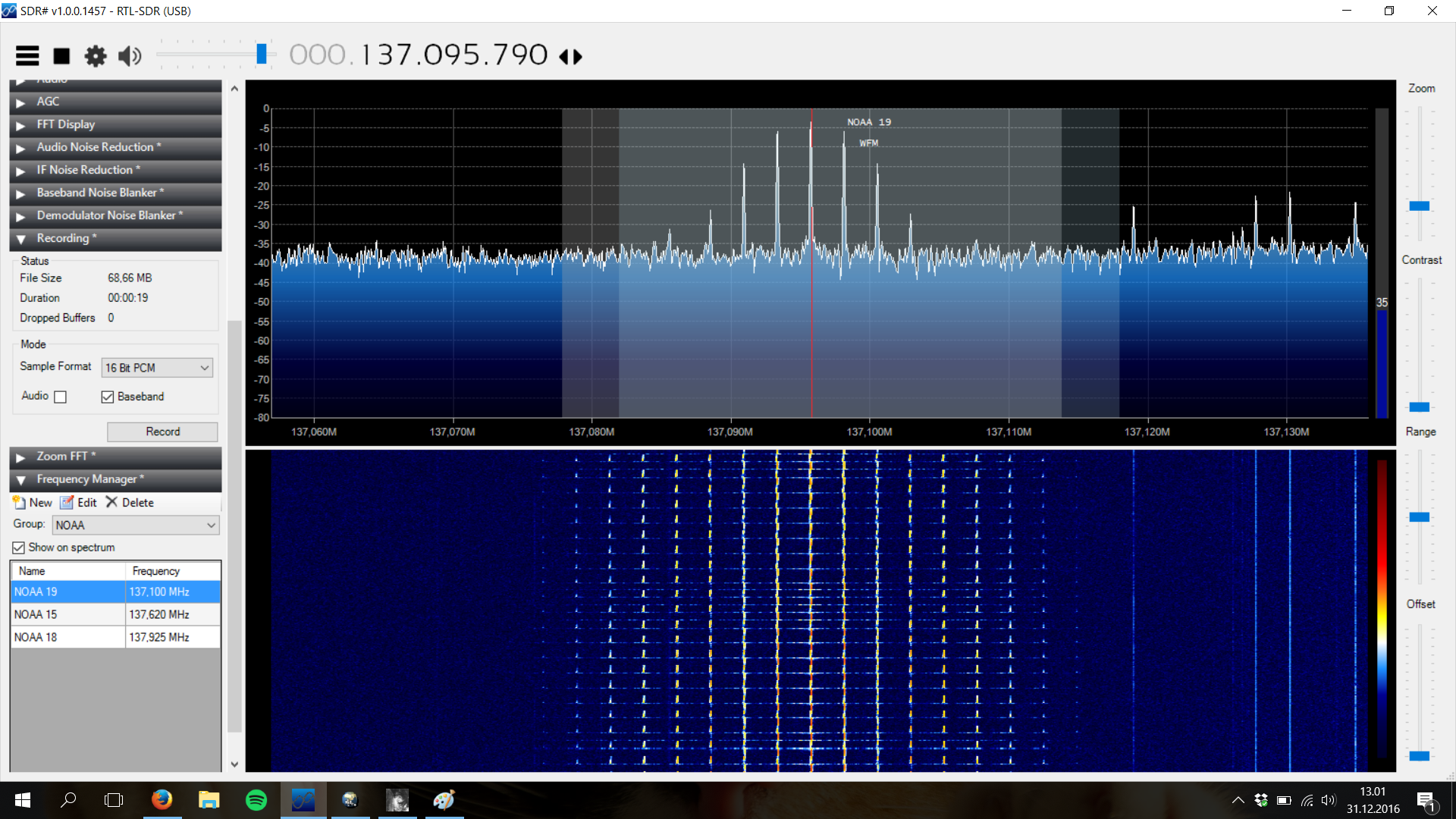
I should mention at this point that there are two main weather satellite groups which are in operation and can be listened to. The one group is the National Oceanic and Atmospheric Administration (NOAA) satellites, of which three are in active duty today (January 2017). These are NOAA-15, NOAA-18, and NOAA-19. Their current status can be checked here. The other group is the Meteor satellites, of which the Meteor M1, and Meteor M2 are in orbit. Only Meteor M2 is still transmitting. Both of these satellite groups transmit in the range 137-138MHz, and both groups use right hand circular polarization. So one antenna is all you need! The reason for using circular polarization is that the satellite will change it's orientation relative to a stationary listening station on earth, depending on where in the sky it is. And since a satellite seldom passes directly overhead, the exact angle between you and the satellite will always be changing. This is where the strength of circular polarization comes in, as the orientation difference will not affect the signal strength! The NOAA satellites transmit low resolution images, but are easier to tune into and decode. The Meteor satellite transmits high resolution color images, but correctly decoding and receiving the data is more difficult in my experience.
Band pass filter and LNA
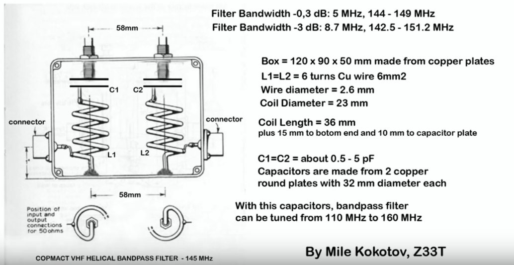
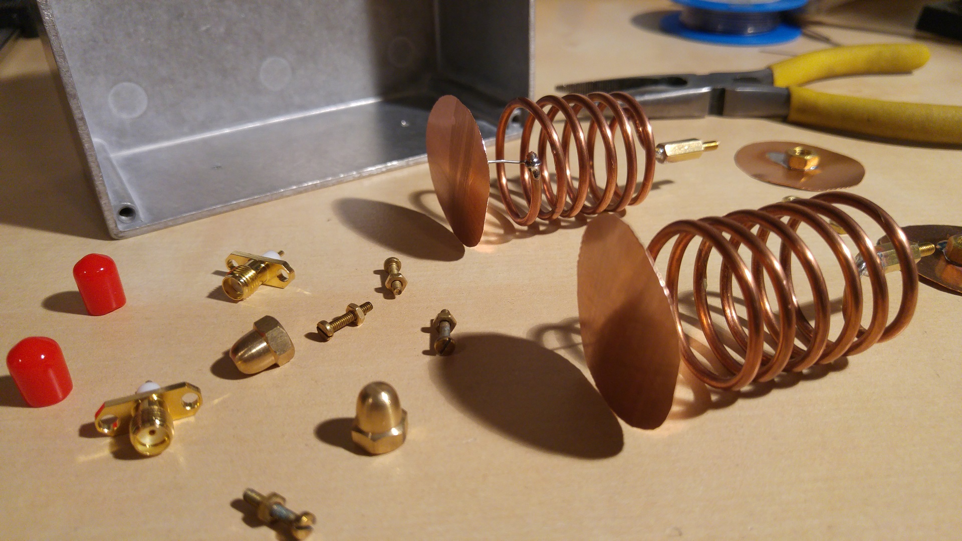
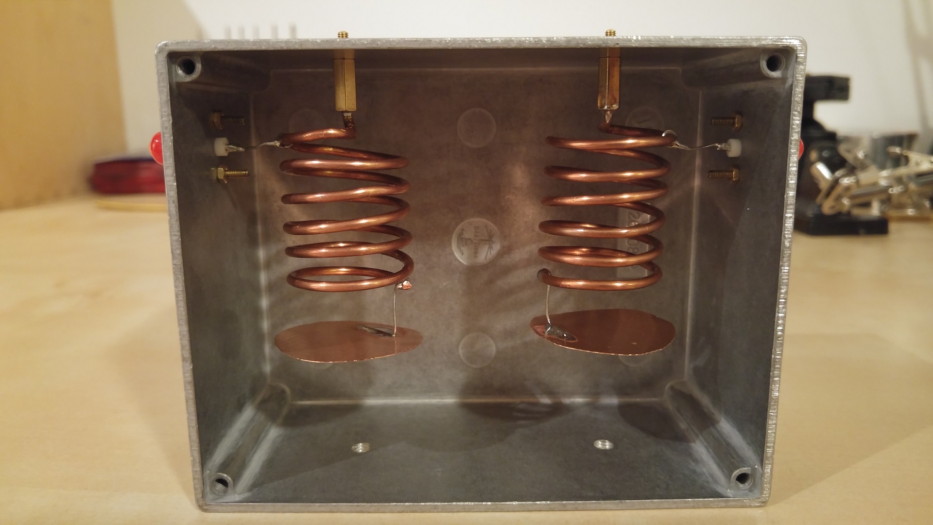
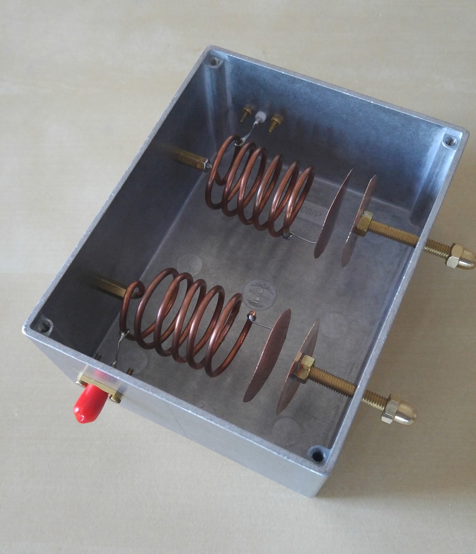
To ensure I was getting the most out the limited signal I was receiving from space, I also applied some additional analog pre-processing to the signal before it even reached the SDR. I constructed an adjustable band-pass filter, to limit interference from out of band signals (FM broadcasts, GSM, etc.) It's bandwidth is about 12MHz, which is fine for filtering out most noise sources in my area. With a band-pass filter I can increase the gain in the system, without having out of band signals overload the amplifier and/or RF input. I followed the construction details given in this youtube video. Since the filter is tunable, exact measurements aren't critical.
Band-pass filter construction. During use the lid is screwed on, to keep out external noise.
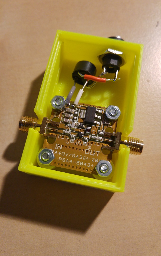
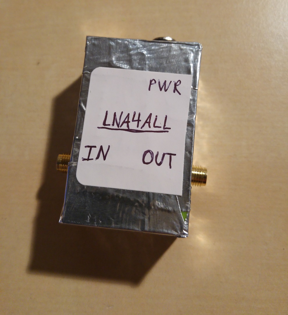
The second stage of signal pre-processing was to use an external low noise amplifier, or LNA. I chose to use the Lna4All, which has received many great reviews, and has good specs. I found that even with the LNA, I needed to increase the internal gain of the SDR fairly high. This was due to the loss of the band-pass filter, and also how weak the received signal is to begin with. I have made a 3D-printable housing for the Lna4All, which can be covered in aluminum foil for shielding. After shielding the LNA, I noticed a large drop in background noise levels, so I highly recommend doing this.
Low noise amplifier, Lna4All
Tuning of antenna
In an attempt at tuning my antenna for optimal reception, I invested in a white noise source, a directional coupler, some SMA connectors, and some 10dB attenuators. I followed the tutorial here to learn the basics: Measuring filter characteristics and antenna VSWR with an RTL-SDR and noise source.
The basic idea is to send noise through the coupler to the antenna, and measure what is reflected back. This is compared against the reference of full reflection from the source, which is the case when nothing is connected to the coupler output (z = infinity). For frequencies which the antenna is particularly good at transmitting (and per extension receiving), very little power will be returned. Conversely, frequencies which the antenna is unable to transmit will be largely reflected back to the source. By plotting these powers for a number of frequencies, the relative performance of the antenna can be determined for every frequency, giving a reflection coefficient at each frequency. Keep in mind that the numbers will be statistical in nature, as the antenna still receive external signals during this measurement process. So if a local transmitter is sending near your antenna, this may turn up as "more reflected power" when you plot the reflection coefficient, making the apparent reflection coefficient seem worse than it actually is.
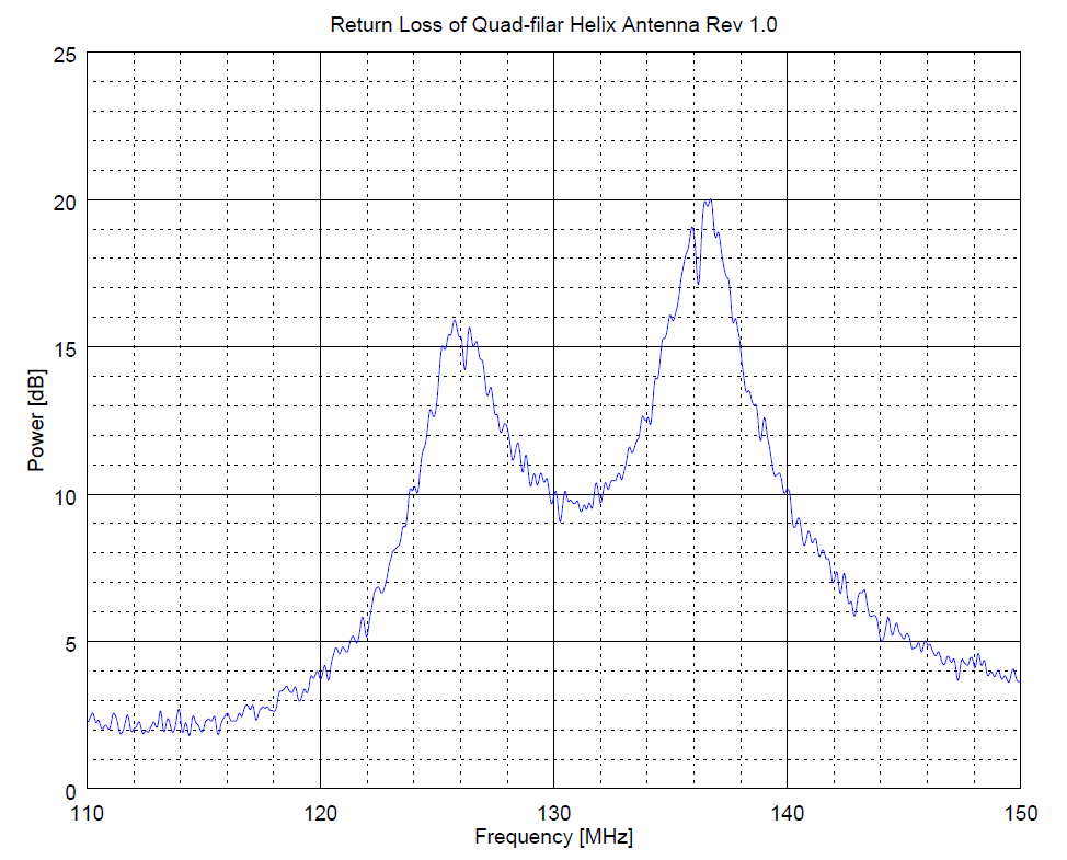
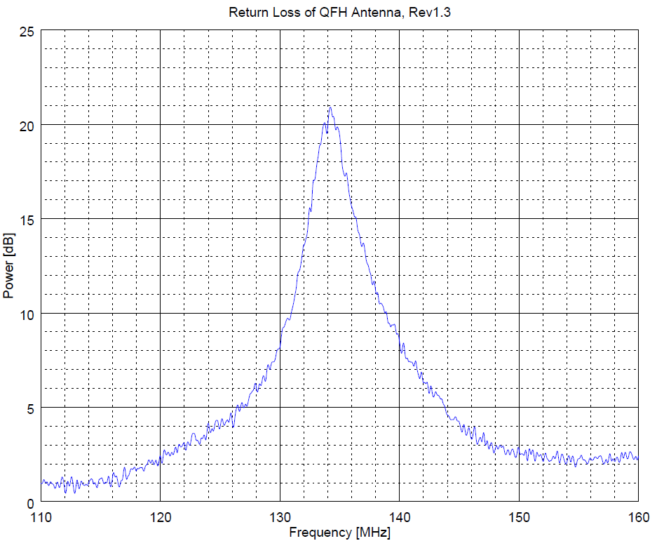
Comparison of the return loss between the first revision, and final revision of the antenna.
For the QFH antenna, there will be two resonant frequencies, visible in the plot as two spikes. I'm not sure how to interpret this, and what is the desirable condition. The initial scan of my antenna revealed two distinct resonance points. One at the desired reception frequency of 137MHz, and another down at 126MHz. Because of their proximity the antenna had a VSWR below 2 from 124 - 140MHz, and hence a fairly wide bandwidth. This might have been intentional on the part of the calculator I used, although I'm not certain. Either way, I'm only really interested in the frequency band of 137.0 to 138.0MHz, so narrowing the bandwidth of the signal will help reject out of band signals. Since the upper resonance point was roughly in the right place, I started by trimming 1cm lengths from the larger loop, until it was closer to the upper resonance point. Eventually I was able to converge the two resonances, resulting in an antenna with decent selectivity for 137MHz. I'm unsure if this modification has had an impact on the polarization however.
Software used, and applicable settings
Satellite Tracking
To know when I should attempt to receive a satellite transmission, I use gpredict. Pretty much any satellite can be added to the scan filter, which will provide information on when the next pass will be, along with direction, elevation, and other relevant data. On my Android phone I use ISS Detector with the "Amateur Radio Satellites" extension.
NOAA
It seems a SNR of at least 25dB is needed to create a decent image from NOAA transmissions. I didn't take the time to set up Orbitron, or other tracking software, and instead corrected for the Doppler shift manually. This is very easy, and has no effect of the received signal if done correctly. Set the bandwidth to something wider than 34kHz (I use 36kHz), and you will only have to correct the center frequency before your signal begins to fall outside of your bandwidth. This happens slowly enough that you can do it by simply watching the signal in real-time. I used a sampling rate of 1.4Mps. I was only able to produce an image in wxtoimg if I used the audio piping method. Saving raw recordings to disk and opening did not seem to work. I used VB-CABLE for piping audio from SDRsharp to wxtoimg. The tutorial here was most helpful.
SDRsharp settings for NOAA satellite reception
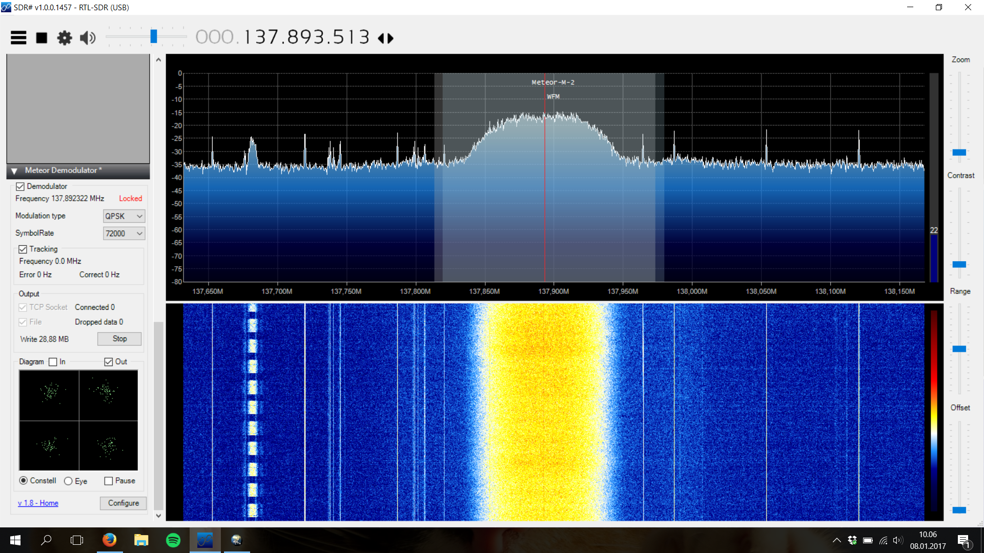
Meteor
First apply the SDRsharp plugin "QPSK Demodulator Plugin" found on the list of SDRsharp plugins, and then download M2_LRPT_Decoder.
Unpack it and create a .ini file with the same name as the executable, and fill it with the following:
[OUT]
path = C:\AMIGOS\Images
rgb = 122.jpg
rgb_q = 100 m
logs = NO
APID70 = NO
VCDU = NO
Now you should be ready to capture and decode Meteor satellite signals. Like the NOAA satellites, I didn't bother with automatic Doppler shift tracking. I simply found the signal near where it was expected, and had the demodulator lock on to it. With a wide enough bandwidth (160kHz) no further adjustment is required. Once these signals locked, the lock was maintained even as the SNR was reduced to 10dB. I found that the frequency control should NOT be touched once locked, or the lock will be lost. Regaining it can take a long time, or never happen if the signal is too weak. Check off file as output, and modulation QPSK, 72000. Choose the output directory in the configure menu. Tune in the the satellite frequency, and check off Demodulator. I used a sampling rate of 1.4Mps. Once a lock is achieved the Write counter will start pouring out MBs to a .s file, which will be placed in the output directory once the pass is complete. Open this file with M2_LRPT_Decoder. Once it finishes processing, press "Generate RBG". The image is complete! I can recommend the tutorial here, which helped me get things working.
SDRsharp settings for Meteor M2 satellite reception
Closing thoughts
There also seem to be some null points on my antenna, though this may be due to the location it is placed in. I found that pointing the top of the antenna towards the satellite seems help with satellites north of the antenna. I'm not sure why this is, but it could be local geography, interference, or just a property of the antenna itself. Incorrect phasing of the two loops will cause radiation pattern issues, which is my primary suspicion.
Disclaimer:
I do not take responsibility for any injury, death, hurt ego, or other
forms of personal damage which may result from recreating these
experiments. Projects are merely presented as a source of inspiration,
and should only be conducted by responsible individuals, or under the
supervision of responsible individuals. It is your own life, so proceed
at your own risk! All projects are for noncommercial use only.

 This work is licensed under a
Creative Commons Attribution-Noncommercial-Share Alike 3.0 Unported License.
This work is licensed under a
Creative Commons Attribution-Noncommercial-Share Alike 3.0 Unported License.