This
entire project has been made obsolete by RTL-SDR and other lost
cost/effort SDR solutions, which are cheaper, better, easier to use,
and supported by a large community. Presented for curiosity's sake.
28.02.10
This project was largely inspired by
this Swedish
guy's TV tuner projects (be sure to see the rest of his site) which
caught my attention because a) all the heavy lifting is done by the TV
tuner and b) the reception range is massive! Basically what one does is
interface with the TV tuner, which is easy for the older analog tuners
and more invasive for the newer digital tuners. The TV tuner will
provide a constant 38,9MHz intermediate frequency output here in
Europe, or 45,75MHz overseas. To hear what the TV tuner is receiving we
need to demodulate the IF from the tuner, which can be done using any
old FM radio after a little hacking. Quite simply, the FM radio is
modified to receive at the intermediate frequency of the TV tuner.
Since TV broadcasting went digital last year
here in Norway, internal TV tuners have become obsolete so acquiring
one is no problem. In fact, the TV you harvest a tuner from can still
be used afterward to watch movies and such via the external input
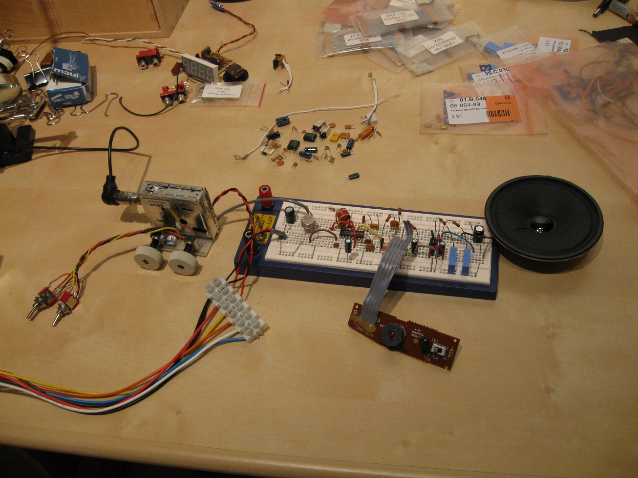
(scart, composite, s-video, etc). The tuner itself is the shielded box
with an
antenna input, which you can see in the above picture. I forgot to take
a close up of it, but the Swedish guy has a thorough explanation of
tuners
if you need more info.
I knew I could harvest a tuner, but I didn't know whether I could
modify a radio or not. Prior to this project I had no knowledge of radios,
believe it or not, so this was all new to me. I had a cheap radio in my
parts bin which was of no interest to me before, but suddenly now
became appealing. Inside it had two ICs, one for audio amplification
(TDA2822), and one AM/FM reception and demodulation (TA2003). In
addition to these two valuable chips there was also a 10,7MHz filter
and discriminator which I could use to demodulate the IF signal, and a
variable capacitor. Basically everything I needed. By
tracing the PCB and making a schematic over the radio I was able to see
what needed to be modified.
The TDA2822 is just wired up like they
show in the datasheet with an AF filter on the input. The TA2003 is
fixed so it only receives FM at 38,9MHz. The IF at 38,9MHz goes through
the SAW filter which removes the frequency components far above this
which result from frequency mixing. The now much cleaner IF signal goes
into the TA2003 chip and is mixed with the frequency determined by the
LC circuit on pin 13, which should be 38,9 - 10,7 = 28,2MHz. The
resulting 10,7MHz signal is then sent through a filter, and finally to
the demodulator. The discriminator on pin 10 is used to extract the
audio signal. The final demodulated signal exits the chip at pin 11 and
is sent through some audio filters before being amplified. There's a
lot of
complicated theory behind all of this, but thanks to integrated radio
ICs you don't need to know much of it to make something that works. :-)
IMO the neatest thing about this project is that everything you need
can be scavenged from one transistor radio and a TV. And the TV works
afterwards! The above circuit
was designed using what I found in the radio and had at hand, so
some of the components values may seem arbitrary, which they are.
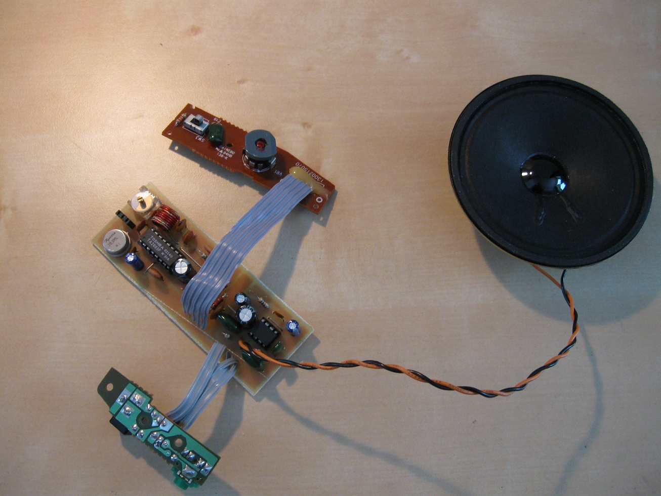
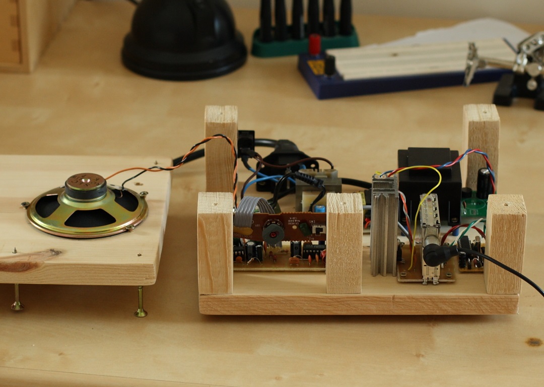
Completed 38,9MHz IF demodulator. Notice how the volume and input jacks were recycled.
In the end I was able to pick up all of the local FM stations, along
with several unidentified signals in the other bands. The number of
signal sources I could find increased greatly after building the
circuit on a PCB. The PCB files aren't provided because chances are the
radio IC, SAW filter or audio amplifier you find will be completely
different. I plan on finding a digital TV tuner before making a project
box for this.
TV Tuners
Analog: The particular tuner I used for this project has the
serial number UVE33-EW51 and was found in a small 12 volt TV. I
couldn't find any information on it, which I assume is the case with
any tuner found out there, but fortunately the pins were labeled as
seen in the above schematic. Every analog tuner will have equivalent
pins so it's just to find out which are which. Pins Bu, BH and BL
select the band you are listening on. Knowing what the frequency range
of these bands isn't easy though, and they're not always standard to
make things worse. I can
only place the frequencies in the FM band, so I'm guessing that BL goes
from 40MHz to 106MHz, and BH continues from there up to 180MHz. Bu
could be anywhere in the UHF band. I know the channels on the TV were
1-26, so using this
knowledge I could probably find the exact band frequencies if I wanted
to. MB is the 12V supply voltage, AGC is automatic gain control, which
sets the gain. Set this to 6-10V and you should pick up something.
Below 6V and my tuner didn't receive anything. VT is the tuning voltage
input, and varies from 0 to 13V to get the full range on my TV tuner.
Most tuners use 0-30V however, so keep this in mind. Taking the 30V
supply from the TV might be a good idea. IF is intermediate frequency
out, of
course. So as you see using the old analog tuners is great to get
things up and running, but not so great when you want to actually use
the device. :-) Frequency is unknown, you'll drift because Vtuning
isn't constant, etc.
Digital: All of the
flaws and benefits of the analog tuner are nullified by the digital
tuner. In this tuner the receiving frequency is set digitally, and
maintained by a PLL. This means you can tell which frequency you are
listening too quite easily. However interface is much more difficult,
because you need to communicate with PLL and synthesizer chips to set
the receiving frequency. The
plus side is these things use I2C, which is a standard.
33V Tuner power Supply
Update 11 July 2013
The digital TV tuner I found required a 33V source to function, so I built
a simple boost converter to step up the voltage to the required level.
I was having severe problems with noise when using the tuner with this
power supply, until placing a few decoupling capacitors in the
circuit. A 100nF cap was placed at the supply, while a 10nF capacitor was
placed directly across the vTuning leads on the tuner. This eliminated
noise problems altogether, and the tuner is now run from a mains powered supply.
Digital TV tuner Radio
I found a digital tv tuner of the type UV1316, which is I2C compatible.
It requires a +33 and +5 volt supply, but is otherwise quite easy to
use. The intermediate frequency output can be plugged into the circuit
above. To control the tuner, I constructed a simple circuit consisting
of a microcontroller which received control signals over bluetooth. The
circuit would then decode the bluetooth data, and write data to the
appropriate registers in the tuner via the I2C interface. An Android app
was written which would translate the desired listening frequency into
the correct register values, which are then sent to a connected
bluetooth unit. The required circuit is nothing but support
circuitry, so no schematic will be provided. The android app and
microcontroller firmware can be downloaded here.
Disclaimer:
I do not take responsibility for any injury, death, hurt ego, or other
forms of personal damage which may result from recreating these
experiments. Projects are merely presented as a source of inspiration,
and should only be conducted by responsible individuals, or under the
supervision of responsible individuals. It is your own life, so proceed
at your own risk! All projects are for noncommercial use only.

 This work is licensed under a
Creative Commons Attribution-Noncommercial-Share Alike 3.0 Unported License.
This work is licensed under a
Creative Commons Attribution-Noncommercial-Share Alike 3.0 Unported License.