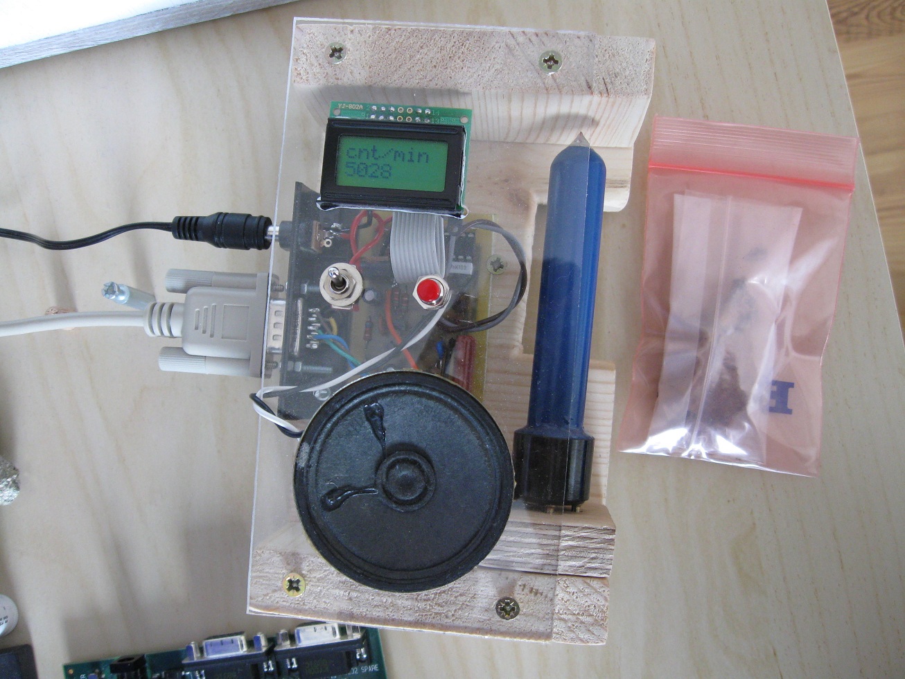
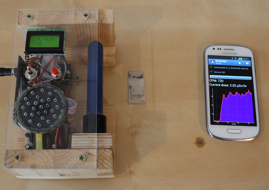
Geiger Counter connected to PC, displaying counts/min from a
pitchblende sample.
The first Geiger counter I built was little more than a toy in terms of
practical use, due to it's very limited sensitivity. It also lacked any
indication of radiation level beyond your own ability to determine the
repetition of pulses, which for my part only allowed me to tell if
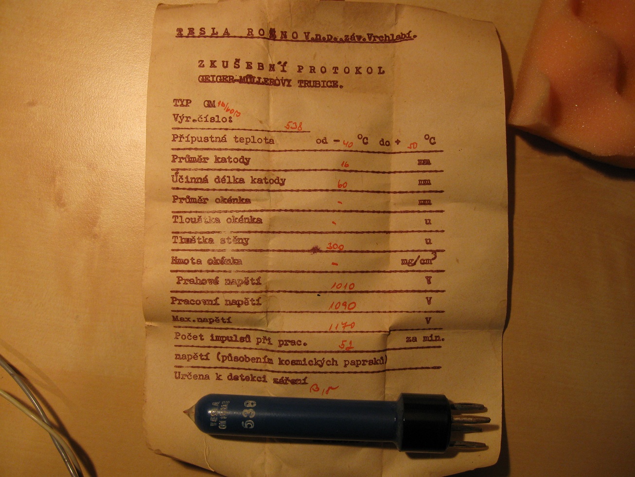
there was a little radiation, some, or lots. So Stella was so kind to
donate a few Czech Geiger tubes from the cold war. They were made
quickly some time in the 60's, most likely for a cheap, mass produced
Geiger counter, which makes it amazing that some of them still work to
this day. The Geiger tubes use an an organic quench gas
(methanol or isobutane), and as such require a higher operating
voltage. These tubes have a much larger area
for ionizing particles to hit than the tiny SBM-21, and thinner walls
so fewer will be
stopped before they can ionize the chamber. The thinner wall and larger
area makes the tube much more suitable for detecting X-rays,
which is the primary use of my Geiger counter.
I had purchased some small 8x2 character LCD displays, and combined
with a microcontroller the counter could display all sorts of
data based on the
counts from the Geiger tube. Not only that but the raw count data could
be sent directly over a serial connection to a PC, thus allowing for
remote monitoring of radiation levels. The count values could then be
analyzed later using and graphed using a spreadsheet program. With this
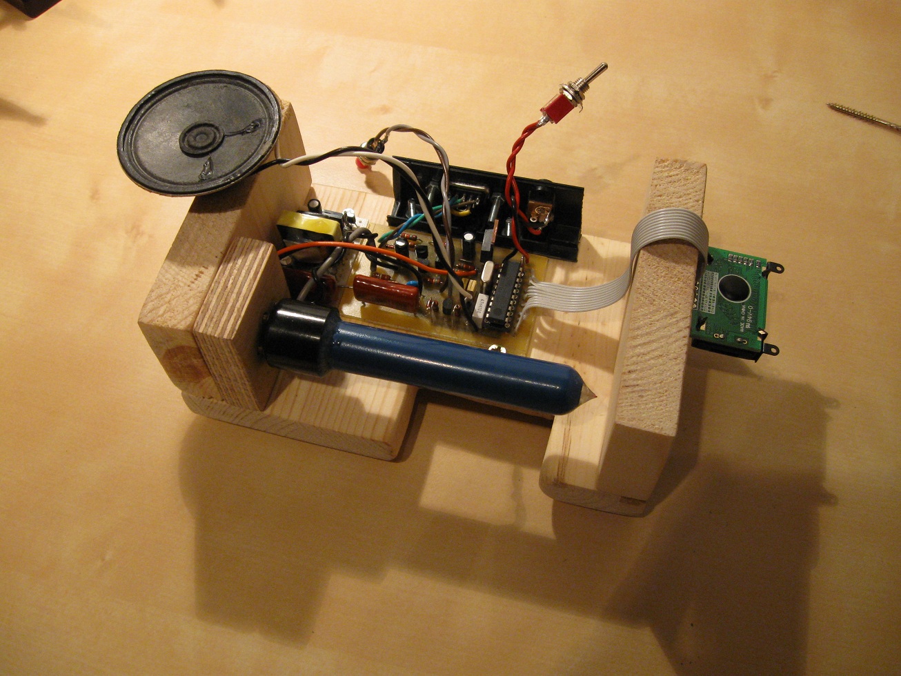
goal in mind I started constructing my next Geiger
counter.
Nothing
new or clever with the circuit design, except for the discrete
RS-232 level converter perhaps. I only did that because I didn't have
any MAX232 chips at hand, and communications are one-way. Feel free to
use a MAX232 instead. The high voltage supply for the Geiger tube is
another story. I needed something small, quiet, and efficient to
provide a clean, regulated 1100V for the tube. This proved to be the
biggest headache with the entire
project, and took several weeks to perfect, probably because of my
lacking insight in flyback transformer design. The basic schematic was
determined fairly quickly, essentially being the same type I used for
my first Geiger counter. PCB, firmware, schematics and PC program can
be downloaded here.
The transformer was the difficult part, as
many would work, but they would give either too little voltage, or draw
too much power. I had to play with several different core types and
windings until I found a design that worked alright. Quite simply I had
to use as many turns as possible. I would first wind several layers of
thin wire for the
secondary, and then stuff as many primary and feedback
windings in as possible. I believe the winding inductance is
the most important figure here, so they've been marked on the
schematic, not turns. (I didn't keep track of them anyway) The core
type I used is unknown, but came from one of those
"base-drive-transformers" used in TVs and monitors for the horizontal
output transistor. The main
drive transistor was also a sore point, and had to be just the right
kind in order not to dissipate too much power, or for the output
voltage to droop with time. None of this was done empirically, so I
can't give any more pointers than that. I found my transformer was very
noisy, to remedy this I dipped it in hot wax a few times to seal the
windings. This damped the noise almost entirely. If you want to build
this
project, be sure you can construct a high voltage supply for the tube
first, as this is the hardest part of the project.
The firmware for the ATtiny2313 uses the T0 input as a clock source for
Timer0, which simply fills up a 16-bit register. Timer1 is used to
generate an interrupt every second, which then sums up the value from
Timer0 before resetting it. The number of captured events during the
last second are now stored. This number is then sent through the USART
module to a PC, using a simple serial protocol of three start bytes a
255, then data MSB and LSB, and finally an end byte of 128. After
shipping off the count value, the data can then be processed depending
on the state the counter is in. If in accumulated mode, the counts are
simply summed to indicate the total number of events
since
entering accumulated mode. If in "cnt/min" or "counts per
minute"
mode the number of events during the last second are stored in an array
consisting of ten variables. The entire array is then summed up, and
multiplied with 60 to give a counts/min projection based on the last
ten
seconds.
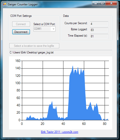
Another fun part of the project was the computer software to go along
with it. I've already made several serial port programs in Visual
Basic, so this wasn't too difficult. I did bump into one problem
though, which delayed this project by three months. The
"SerialPort1_DataReceived" function I used to see when new bytes were
received would only update once every three seconds, meaning for every
three count values I would only get one! This caused me to shelf the
project for several months, and it wasn't until I looked at it again
this last weekend that I figured it out. In the end I had to use a loop
to check
if there were still bytes in the read buffer. Just a heads up in case
someone else runs into the same problem some day. The received count
values are stored in a text file of your choice, and are
formatted so they can be imported into any spreadsheet program worth
it's salt.
Here I've imported the count values using OpenOffice and graphed them.
First several radium watch hands are placed under the tube, then two
americium buttons from some smoke detectors, and finally a uraninite
(pitchblende) sample. It's hard to see, but even the americium give
about ten times background radiation. All samples were measured at four
centimeters distance.
And finally a quick little demo:
Bluetooth logging upgrade
21.07.15
Despite having a serial connection on the Geiger counter, I honestly only used it once or twice.
Setting up a laptop close to the counter, and connecting a serial cable + serial to USB was just too much hassle.
So recently I had some spare time, and decided to make the serial connection wireless using bluetooth 2.1 technology.
In terms of making the counter compliant with the widest range of systems available, I chose to use a Bluetooth Serial Port Profile.
The very popular HC-05 bluetooth module was used for the hardware interface, and is pretty much plug and play, especially if one buys the modules with an on-board 3V3 regulator.
The hardware modification itself was so simple I won't detail it, other than mention that the IO levels were 3V3 on the module,
and 5V on the MCU. Level-shifting was achieved by simply feeding the 3V3 module TX output directly into the MCU RX,
and that a resistor divider of 1k5 + 2k7 was used from the 5V MCU TX output to the module RX. To interface with the Geiger counter
I made a dedicated bluetooth app, which one can see here. The serial protocol used between the counter
and app is detailed there. I have not made a PC application for logging, though this should be rather easy if based on the old application
I used for the wired version. Some minor adjustments will be required to be compliant with the new serial protocol. New firmware for this
Geiger counter can be downloaded here.
The code makes some simplifications in terms of the serial protocol used, but is still fully functional.
It should be possible to interface with the counter using a standard terminal program, see the aforementioned page for details on the protocol.
Disclaimer:
I do not take responsibility for any injury, death, hurt ego, or other
forms of personal damage which may result from recreating these
experiments. Projects are merely presented as a source of inspiration,
and should only be conducted by responsible individuals, or under the
supervision of responsible individuals. It is your own life, so proceed
at your own risk! All projects are for noncommercial use only.

 The firmware for the ATtiny2313 uses the T0 input as a clock source for
Timer0, which simply fills up a 16-bit register. Timer1 is used to
generate an interrupt every second, which then sums up the value from
Timer0 before resetting it. The number of captured events during the
last second are now stored. This number is then sent through the USART
module to a PC, using a simple serial protocol of three start bytes a
255, then data MSB and LSB, and finally an end byte of 128. After
shipping off the count value, the data can then be processed depending
on the state the counter is in. If in accumulated mode, the counts are
simply summed to indicate the total number of events
since
entering accumulated mode. If in "cnt/min" or "counts per
minute"
mode the number of events during the last second are stored in an array
consisting of ten variables. The entire array is then summed up, and
multiplied with 60 to give a counts/min projection based on the last
ten
seconds.
The firmware for the ATtiny2313 uses the T0 input as a clock source for
Timer0, which simply fills up a 16-bit register. Timer1 is used to
generate an interrupt every second, which then sums up the value from
Timer0 before resetting it. The number of captured events during the
last second are now stored. This number is then sent through the USART
module to a PC, using a simple serial protocol of three start bytes a
255, then data MSB and LSB, and finally an end byte of 128. After
shipping off the count value, the data can then be processed depending
on the state the counter is in. If in accumulated mode, the counts are
simply summed to indicate the total number of events
since
entering accumulated mode. If in "cnt/min" or "counts per
minute"
mode the number of events during the last second are stored in an array
consisting of ten variables. The entire array is then summed up, and
multiplied with 60 to give a counts/min projection based on the last
ten
seconds.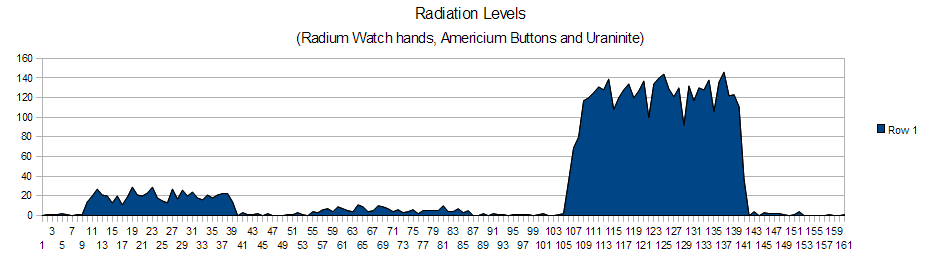
 This work is licensed under a
Creative Commons Attribution-Noncommercial-Share Alike 3.0 Unported License.
This work is licensed under a
Creative Commons Attribution-Noncommercial-Share Alike 3.0 Unported License.