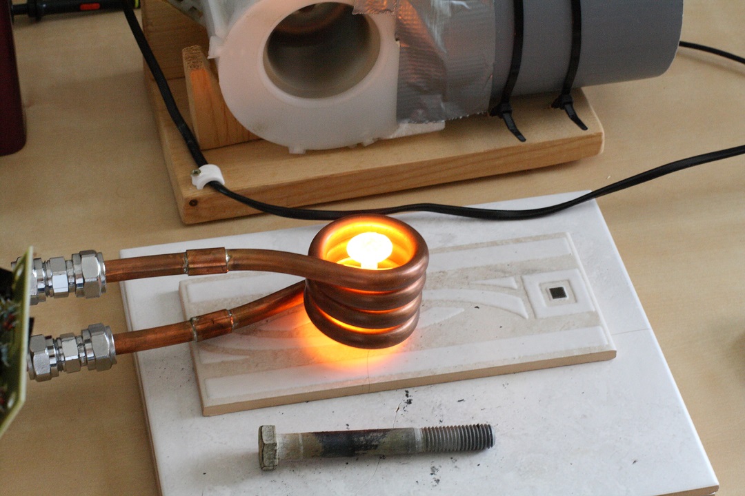
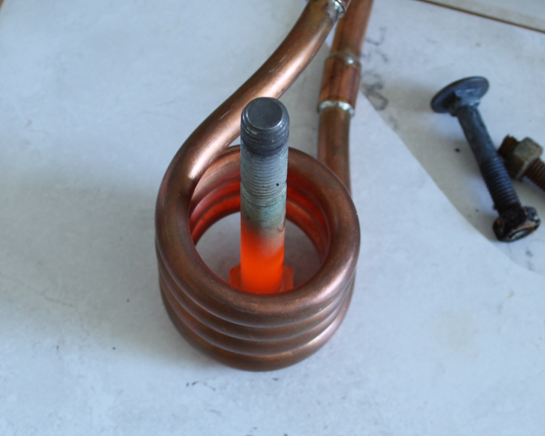
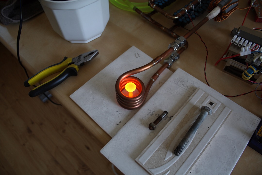
White hot steel carriage bolt, approaching melting point.
This induction heater was designed to be a step up from my previous two attempts, with the end goal of being capable of melting steel. There had been a lot of talk on 4HV about series resonant induction heaters at the time this project was conceived, so I figured I would try that topology, coupled with the success of the PLL driver. I wanted the unit to be robust enough that I could operate the induction heater without risking some sort of failure from misuse. It doesn't take long to forget what the safe operating range is, so it's always better to have the machine do that for you. This was done by implementing a power limit latch which puts the induction heater in a low power state, resettable by a switch. The power limit is triggered by the tank voltage, with the idea being that the induction heaters tank capacitor is many times more expensive than a couple of mosfets. I also designed the power electronics such that they are only run at a current level suitable for the cooling they receive, so I don't need to worry about run times.
Driver Circuit
Resonance is tracked by comparing the drive signal with the tank voltage using the Phase comparator 2 in the PLL chip (4046). At resonance these two signals should be 90 degrees apart. The idea is that the voltage divider allows you to put an offset on the feedback voltage from the phase comparator. Phase comp 2 will pull it's output high when above the target frequency, and low when below. When the frequencies match, the duty cycle will correspond to the phase difference. At 90 degrees phase shift the smoothed voltage from the voltage divider network should be 1/4 of VCO voltage, giving roughly 1/4 of your frequency range. The potentiometer will of course allow you to tune this somewhat. Because of this the frequency range must be selected correctly for the VCO, otherwise a lock cannot be achieved, or the tuning range of the potentiometer will be too short. In the schematic presented, the PLL has a range of 90 - 180kHz, so at 90 degrees shift the VCO should lay at 112kHz or so. The actual drive frequency I used is 102kHz. This difference is tuned in using the potentiometer.
During start-up a resistor/capacitor pair generate a slowly sinking voltage, which is fed through a voltage follower and into the VCO. This slowly drops the operating frequency until the driver hits resonance and the output from the phase comparator takes over (notice the analog OR consisting of two 1N4148 diodes) and holds the operating frequency at resonance. Slowing easing the driver into resonance is also known as soft-starting. The tank voltage is constantly being monitored by a comparator, and once it exceeds the value set by the potentiometer it sets a latch. This latch will in turn reset the soft-start circuit, which raises the operating frequency to maximum. At such a high frequency the tank circuit is merely seen as a light inductive load by the inverter.
Tank Circuit
The tank circuit consists of 140 individual 22nF capacitors, totaling a measured 3,0uF, which I purchased in a bargain on eBay. The ratings of the capacitors are unknown, and they are simply marked with "600V 22nF". Unsure of whether this is the AC or DC rating, I've played it safe and assumed this is a peak DC rating. Which in turn means the AC rating is probably closer to 200V RMS. The tank circuit was soldered together using copper pipe in such a way that the entire thing can be water cooled. If you look closely in the picture above you can see certain sections that have been clamped shut to divert water flow. This tank capacitor layout seems to work well, although distributed inductance in the capacitor connections makes up a large part of the total inductance. Ideally, you want all of the inductance located in the work coil, so it is coupled to your work piece. In hindsight I should have used a larger work coil to improve the ratio between work coil and distributed inductance. To get the same resonance frequency I would also have to reduce the number of capacitors in the bank. The flip side of this is that I would need to increase the voltage stand-off of the remaining capacitors to achieve the same power throughput! Considering that the tank capacitor has a certain impedance at a given frequency, you can easily calculate the current flowing through the tank circuit by measuring the tank voltage. Higher currents means more heat lost in the work piece. Based on this the relationship between tank voltage, capacitor size and work coil inductance, you can estimate the highest current you can expect in the tank circuit. The peak current your tank circuit can withstand should be just a little below the maximum for the capacitor(s) you use in an optimal tank circuit.
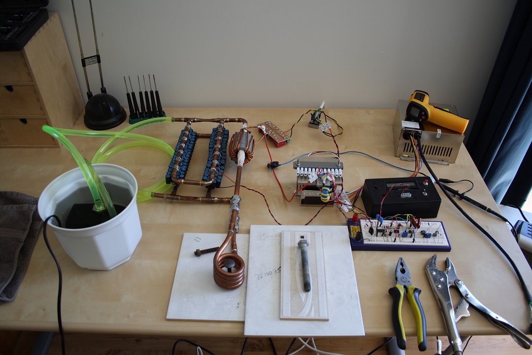
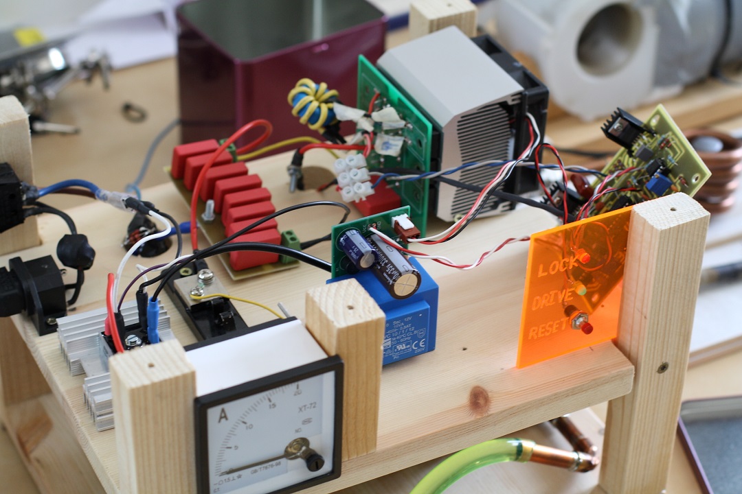
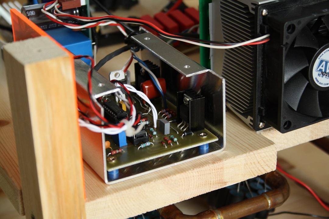
Prototyping stage.
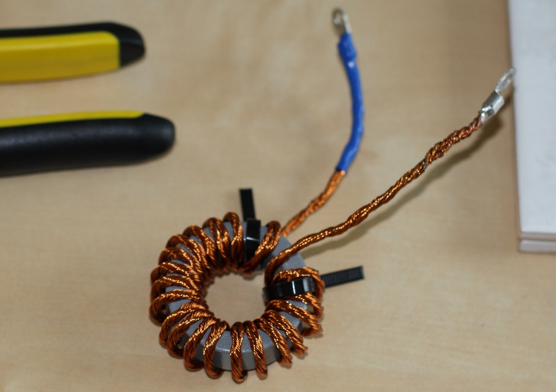
Matching Transformer
The matching transformer matches the impedance of the tank circuit to that of the inverter. After some experimenting with different values I settled on 22 primary turns for 1,6kW at max power. The secondary turn is a segment of the tank circuit. To ensure the losses in the matching transformer were minimal (unlike in my previous attempts) I bought a purpose made ferrite toroid. Things to look for are low core loss at the desired resonance frequency, and a cross sectional area large enough that the flux density is low with the desired number of primary turns. For reference the specs of the toroid I used are presented below. Googling the material code will give graphs over various properties at different frequencies and flux densities. Also I used homemade Litz wire, which was made using 16 strands of 0,25mm IIRC.
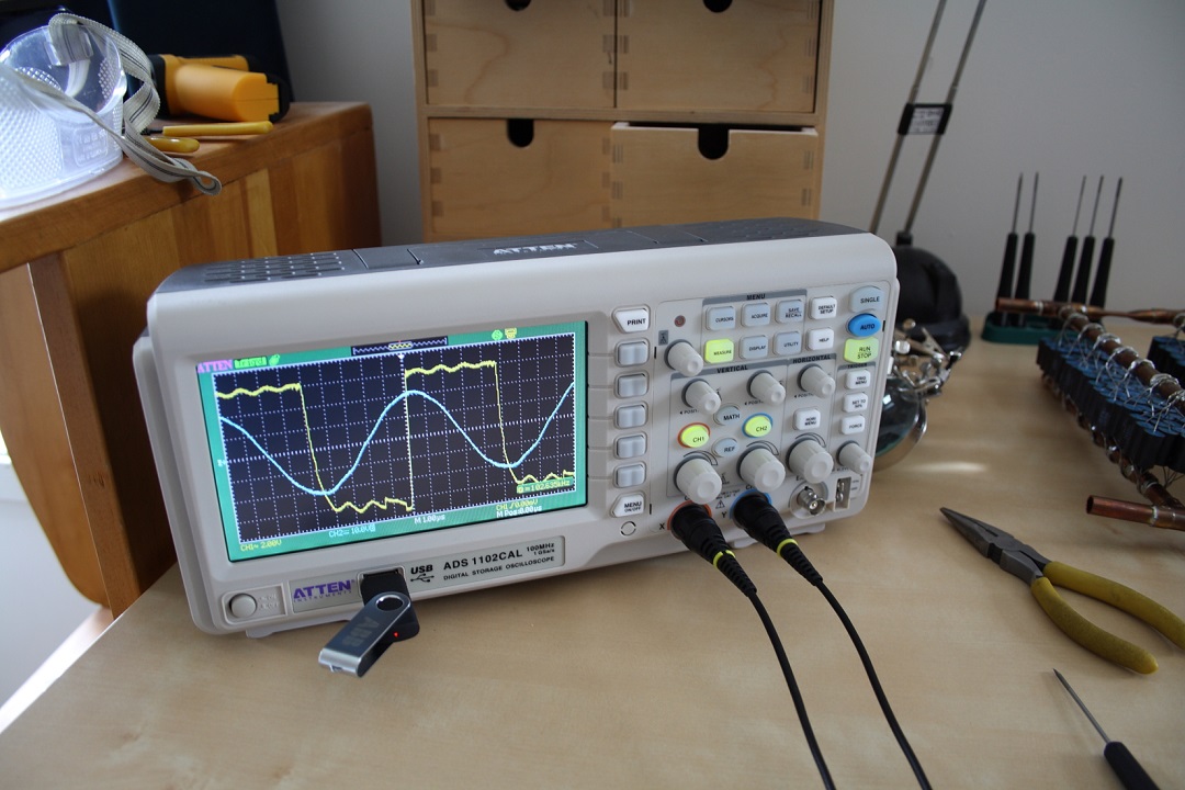
Once constructed, the driver needs to be tuned to resonance. This is fairly straight forward, but keep in mind the phasing of the components is very important, otherwise the driver won't lock, or it will lock at an off-resonance frequency. I didn't make note of the required phasing as there are so many places it can be reversed. If the driver fails to lock, try reversing a phasing somewhere. Assuming the phasing is correct, do this at reduced power and with the intended load in the work coil: Monitor the tank voltage and inverter waveform, and start the driver. The driver should lock at some frequency around resonance. Adjust the phasing potentiometer, and the phase (and frequency) should change. Do this until you reach a peak in the tank voltage, this the peak power point. From this point tune the frequency slightly above resonance. I'm going from memory now, but I seem to recall that this reduced the noise on the inverter waveform significantly. Keeping the driver just above resonance ensures minimal losses in your inverter, and by extension grants you the option to push more power.
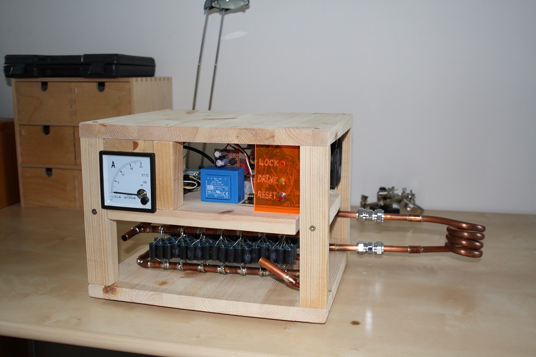
Correct phasing and completed induction heater unit.
Problems encountered:
This project was largely completed in about three weeks during my summer vacation last year. However, it was plagued by a number of problems which I wasn't able to correct until almost a year later. The number one problem was losing mosfets when turning the unit on or off, and whenever the overpower limiter kicked in. I eventually tracked this problem to the slow internal diodes in the mosfets I was using. To remedy this I purchased better mosfets with faster internal diodes, and in addition I also purchased some "blocking diodes". What these are is a schottky diode in series with the mosfet drain, effectively blocking the internal mosfet diode from ever conducting. A fast series diode is then placed in parallel to take over for the internal diode. Since doing this I have only lost one bridge of mosfets, when testing to see what their current limit was.
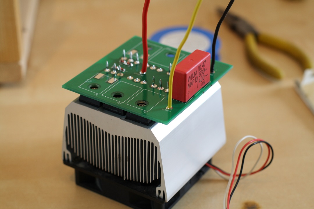
The half-bridge unit. Two mosfets, two high speed diodes and two schottky diodes.
Another problem I encountered was strange behavior from the driver itself. Sometimes it would seem to "fall" below resonance, getting stuck at the lowest drive frequency. When this happened the drive had to be power cycled to return to normal operation. This would seem to happen as the power was increased, and limited me from heating anything beyond a bright red glow. Somehow I discovered that this problem went away when the driver board was placed at an angle, leading me to realize it was induced currents in the board causing the problems! I had placed the tank circuit nearly directly under the driver board, so in hindsight it was pretty obvious that noise would be a problem. I fixed this by folding an aluminium shield around the driver board. Screw holes were tapped in case I wanted to make a full Faraday cage, but this proved unneeded.
Driver board before and after fixing the induced noise problem.
Results
Ultimately this induction heater didn't turn out as powerful as I first anticipated, however it did fulfill my goal of melting steel with an induction heater. An interesting thing I noticed was that the molten steel atop the bolt clumped together to one side, presumably to reduce the cross-sectional area in the work coil. In earlier experiments I've noticed coins will flip and stand upright in a work coil if not held down somehow. When melting the smaller bolt, I had to use welding goggles to protect my eyes from the brilliant white glow from the bolt. Even with the goggles on the bolt appeared bright. Another safety note; galvanized bolts and hardware will emit clouds of noxious zinc oxide fumes when heated for the first time, so do this in a well ventilated area!
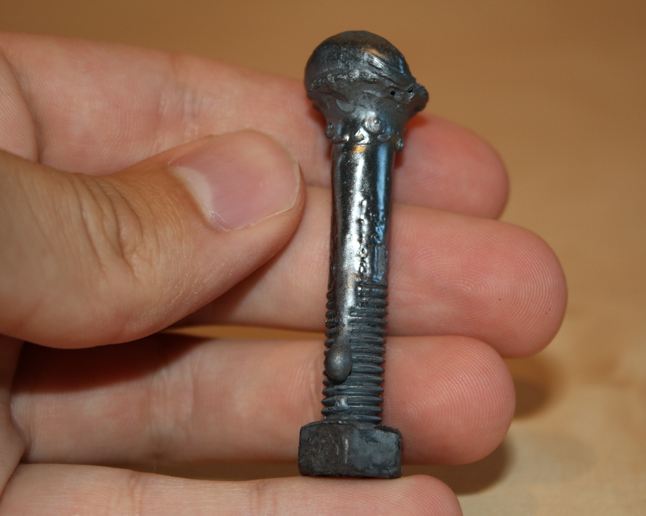
Some bolts at various stages of heating. The same bolt after getting the unit working correctly, melted like wax.
Disclaimer:
I do not take responsibility for any injury, death, hurt ego, or other
forms of personal damage which may result from recreating these
experiments. Projects are merely presented as a source of inspiration,
and should only be conducted by responsible individuals, or under the
supervision of responsible individuals. It is your own life, so proceed
at your own risk! All projects are for noncommercial use only.

 This work is licensed under a
Creative Commons Attribution-Noncommercial-Share Alike 3.0 Unported License.
This work is licensed under a
Creative Commons Attribution-Noncommercial-Share Alike 3.0 Unported License.