Based on my previous two ROV projects, I had a number of improvements I wanted to implement in my next ROV project. However I now had a job, and not nearly as much time or desire to do engineering work in my spare time. Since I started building ROVs in 2010 the open-source community has come a long way, so I decided to become a part of it, and save myself a lot of work in the process. For this project I decided to use the open source ROV project OpenROV version 2.8, for the mechanical design and parts of the electronical design. This allowed me to focus on doing the software and electronics myself. I opted to design my own software and electronics partly because I didn't want this to be a kit build, and also because I wanted a very embedded system, with no need for a laptop in the field. I choose the Raspberry Pi because of it's low price, and since I had become familiar with it during my automatic cat feeder project. Support for wifi and bluetooth were also very important. I'll be honest though, I would have saved time and money by just out right buying a full kit and assembling it myself.
Maiden Voyage
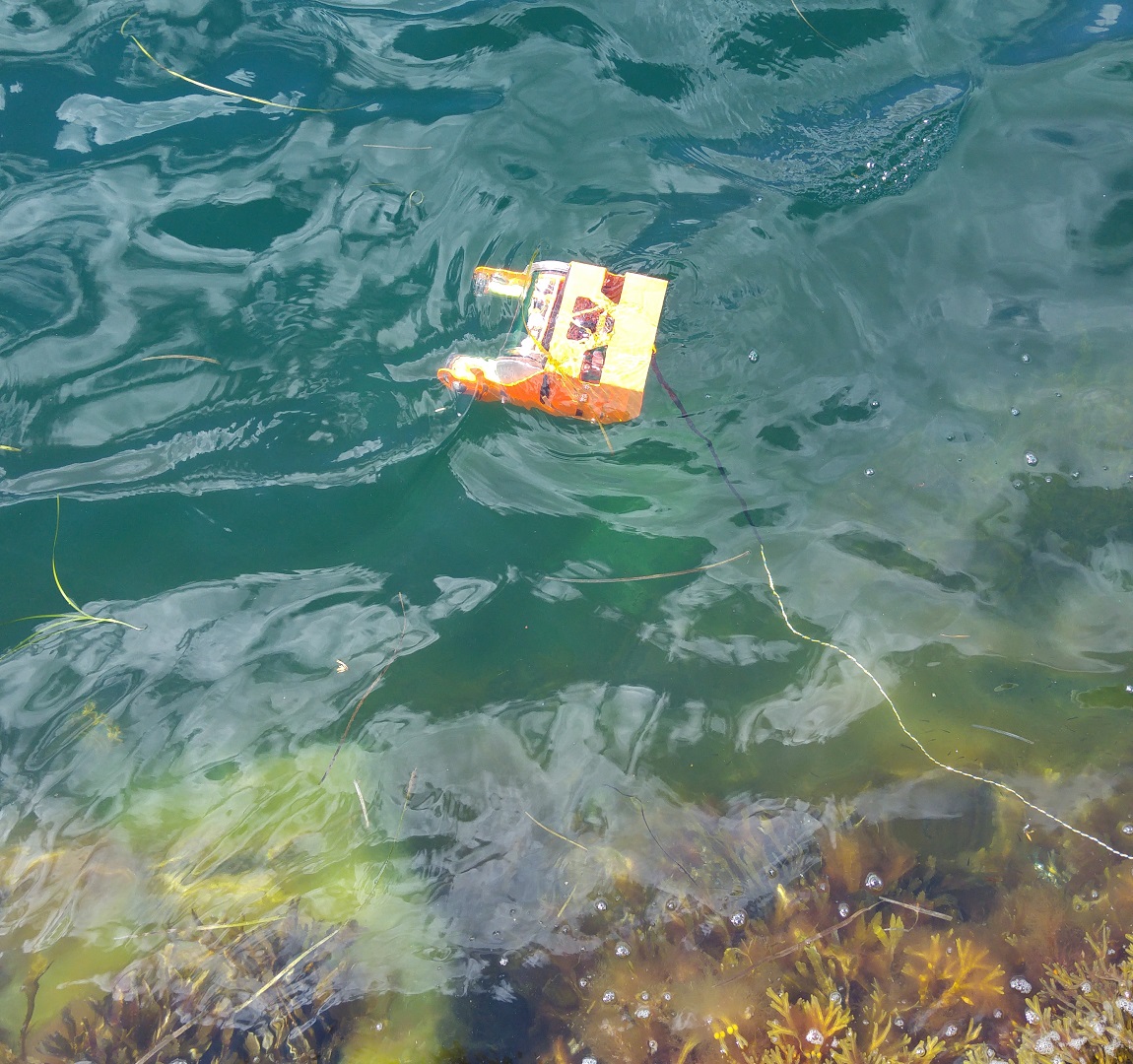
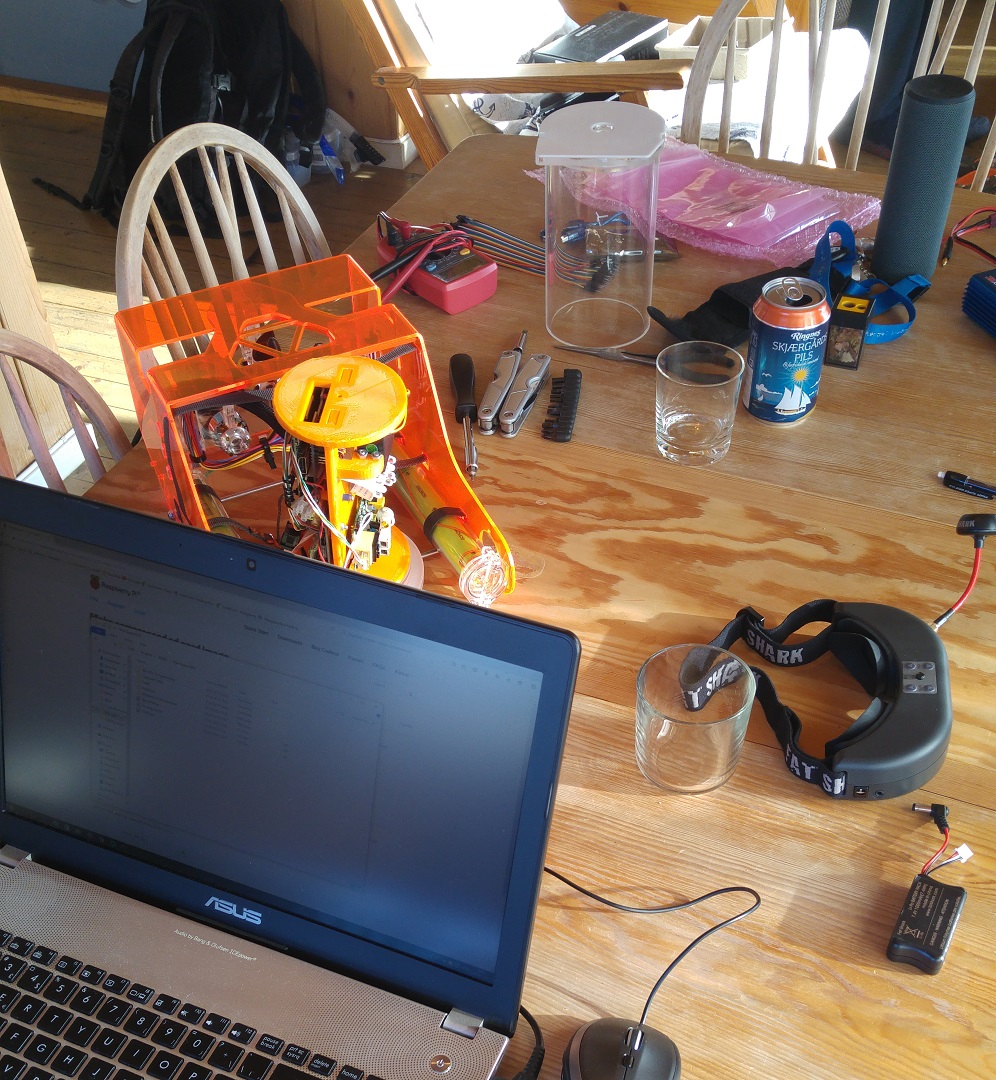
For the first few tests I decided to try the ROV at our summer cabin. This was in part because I didn't manage to complete the ROV before my vacation started, so I had to bring my laptop, and half-ready ROV to the cabin. I had forgotten to program the electronic speed controllers, and after some nerve wracking Internet searches, I found that an Arduino could be used to save the day. As luck had it, I was able to order a cheap Arduino Uno, receive it in the mail, and successfully programmed the speed controllers in just a few days. In the end the ROV project was a success, though I have many things I would like to improve for next time.
The simple life at the cabin
In the video from the ROV, one can see cod, cuckoo wrasse, star fish, and sea urchins. For the first part of the video I explain a little about the ROV itself, the voyage begins about a quarter of the way into the video.
OpenROV construction and assembly
OpenROV has a webshop, which in addition to selling a full kit also sells replacement and development kits. From here I was able to order most of the hardware required, namely:
100 Meter ROV Tether
Cast Acrylic Electronics Tube - 3/16"
Endcap Replacement Kit v2.8
Battery Tube Replacement Kit v2.8
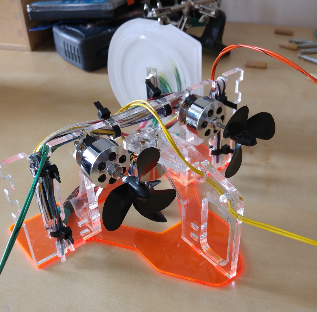
Motor Set
Propeller Set
Which was lucky, as a large acrylic tube cut to the right (imperial!) dimensions was near impossible to find in Europe. Since it wasn't possible to order all of the OpenROV parts from their shop, I also had to order some laser cut acrylic to make the rest of the ROV. Since OpenROV is an open source project, I downloaded the hardware source files, found the parts I was missing, and ordered them from one of the many laser cutting services on the net. I chose to use use RazorLab based in the UK, and I am completely satisfied with their service. So much in fact, that I no longer fantasize about purchasing my own laser cutter.
Assembling the OpenROV components
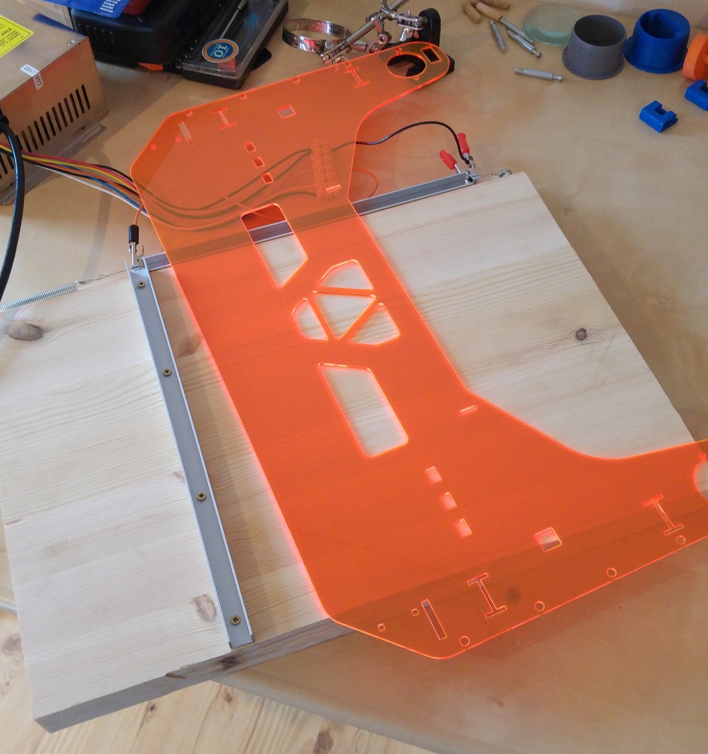
Besides gluing the pieces together, which was tricky, there was one other part of construction I was new to. And that was bending an acrylic sheet accurately. The main shroud which runs over the top of the ROV is made of a single piece of polypropylene plastic in the original kit, but I chose to use acrylic based on cost and the laser cutting services I had available. Getting the right color was of some importance. What I did (which was foolish in hindsight) was to first bend the sheet, and then try to fit it on the ROV skeleton. The bends weren't perfectly square, and I had lost a small amount of length along the top, so it fit much too snug. So snug, that some cracks appeared when I had finally gotten everything in place. In hindsight, bend one side first, then put the main housing inside before bending the other side. This will ensure all parts fit snuggly together, without stress. To bend the acrylic sheets, I made a jig consisting of some nichrome wire and an aluminum trough.
ROV side
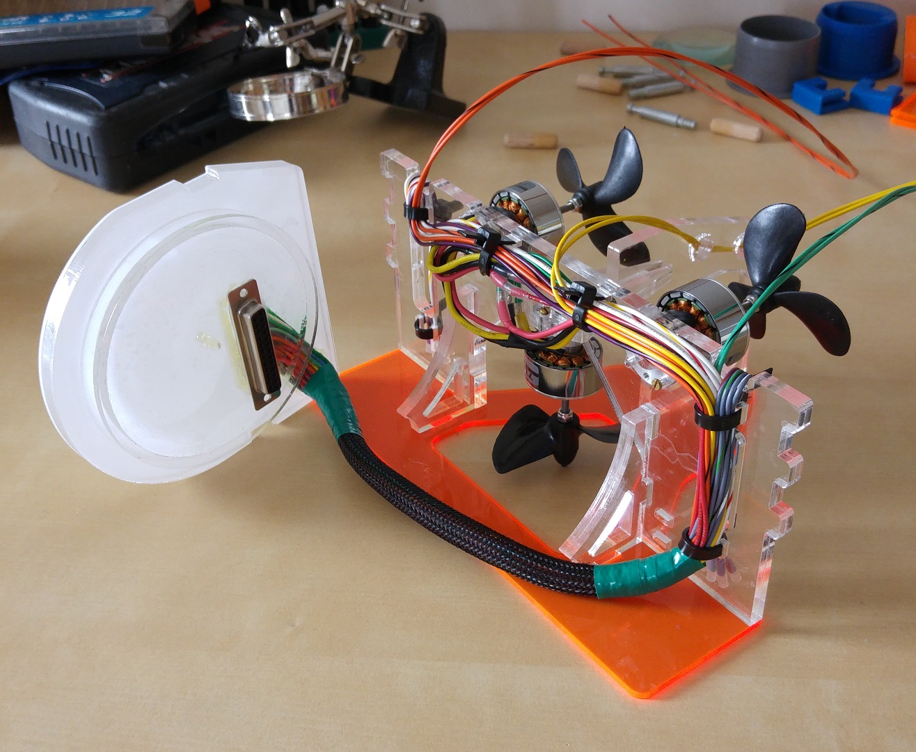
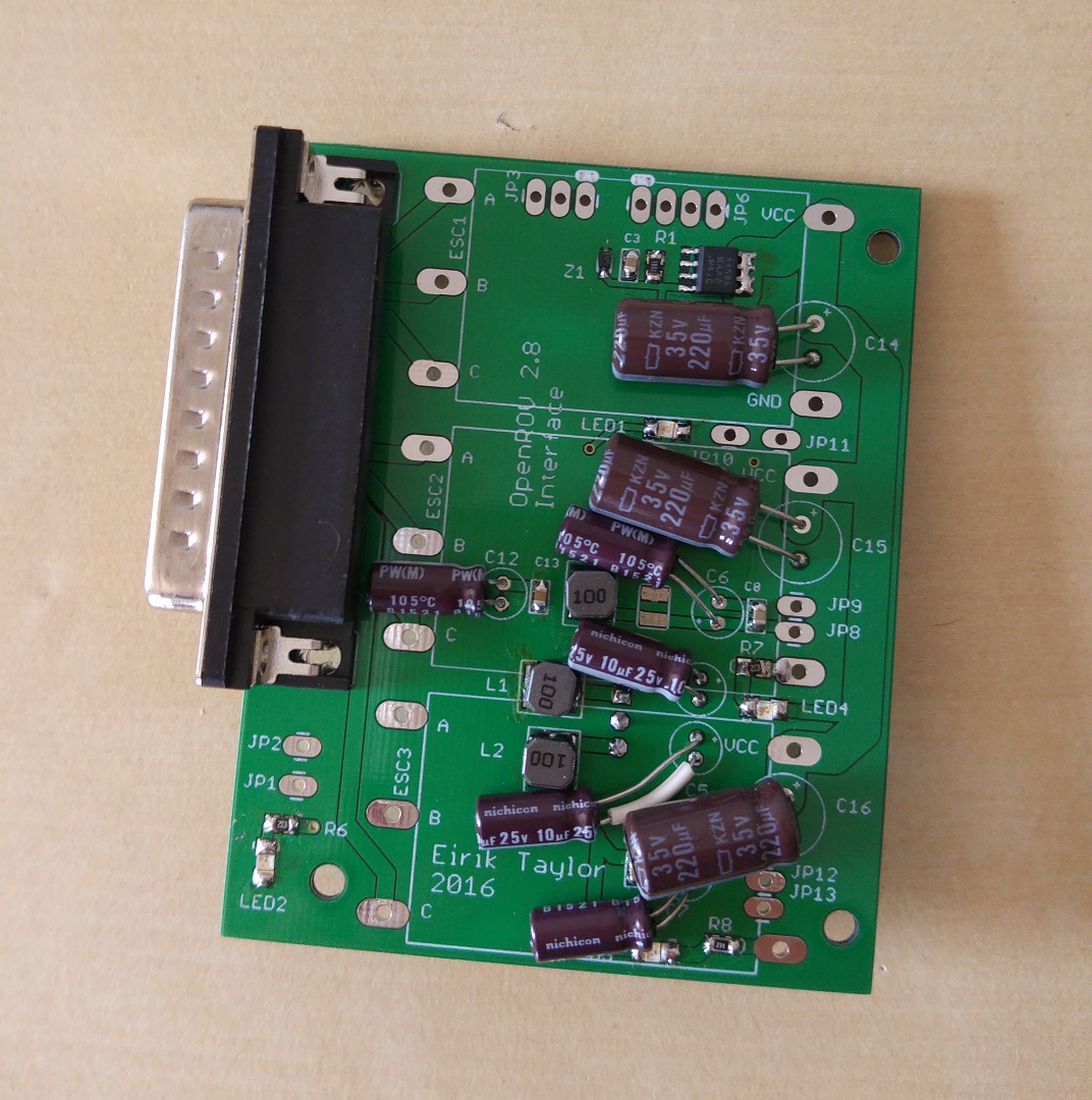
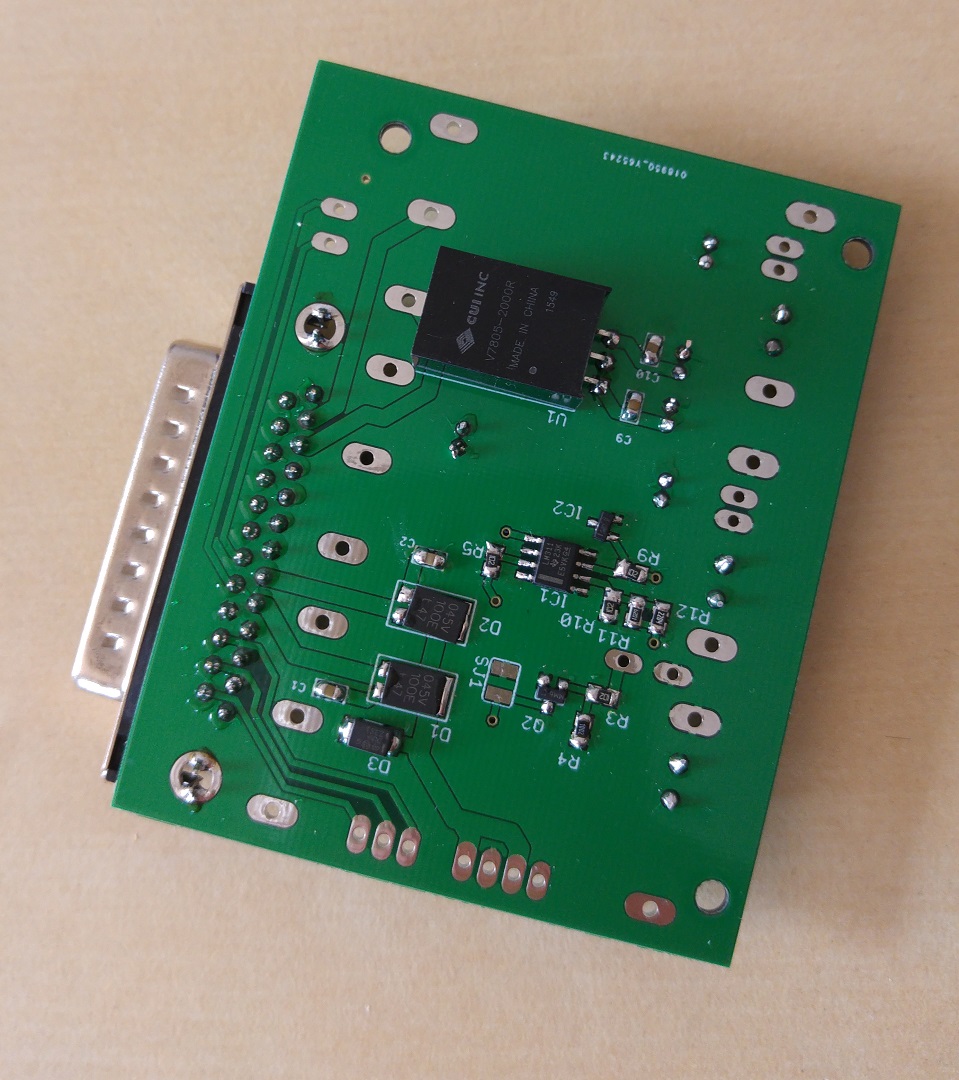
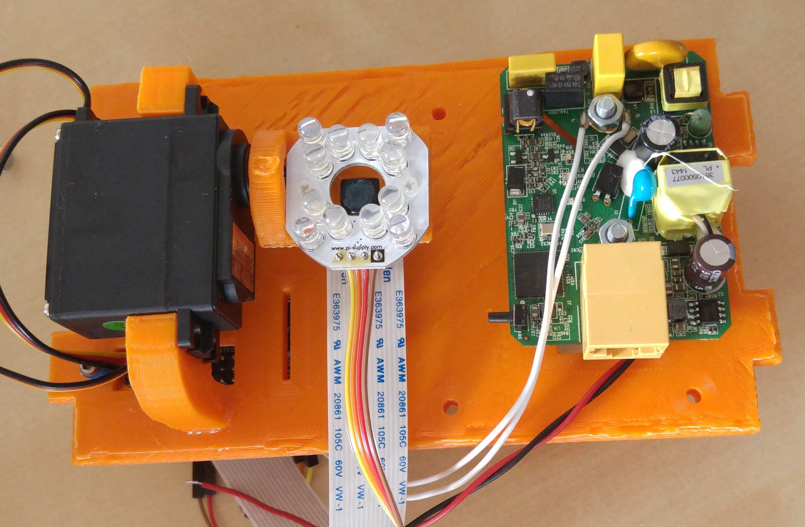
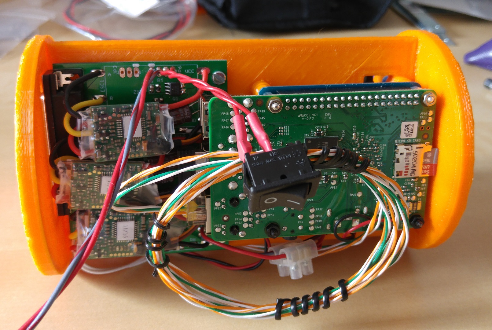
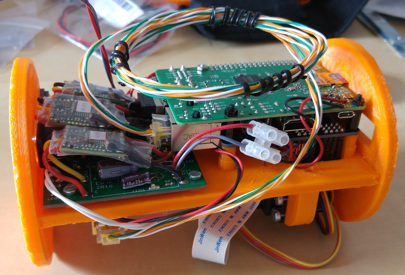
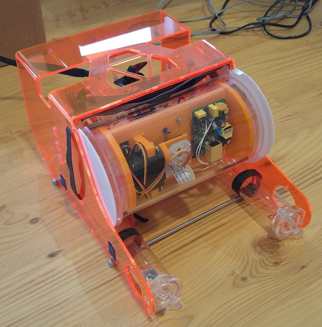
I opted to design a simple interface board which connects to the standard OpenROV 2.8 connector, which in turn can be connected to a Raspberry Pi for control. That way if the electronics failed, I could always order an official OpenROV control board instead and simply plug it in. I decided to also use the same Power over Ethernet solution as the OpenROV, which is the most clever and cheap solution I've been able to find so far. Instead of the specified Homeplug modules I used some ZyXEL modules I found locally. Reverse-engineering the board to locate the low voltage generation section was easy, and I simply injected 12V in at this point. The nominal voltage was 11.4V from it's on-board transformer, but right afterwards this was regulated by a 5V and 3.3V DC-DC converter. The interface board simply holds the electronic speed controllers, a mosfet for switching power to the ESCs, a 5V regulator for powering the raspberry pi, and a comparator to sense when the battery voltage is too low. For light, I used a Bright Pi module, which can be interfaced with over I2C. A simple body was 3D printed to hold the electronics boards in place, and with that the custom ROV hardware was complete. I was having some trouble with my 3D printer at the time, so the print didn't turn out great. The Raspberry Pi on board the ROV was given a wifi dongle, so software upgrades and video downloads can be performed wirelessly.
Schematics, and gerber files for the interface board can be downloaded here. ROV_electronics.zip
The 3D models for the ROV housing can be downloaded here. ROV_3D_printed_parts.zip
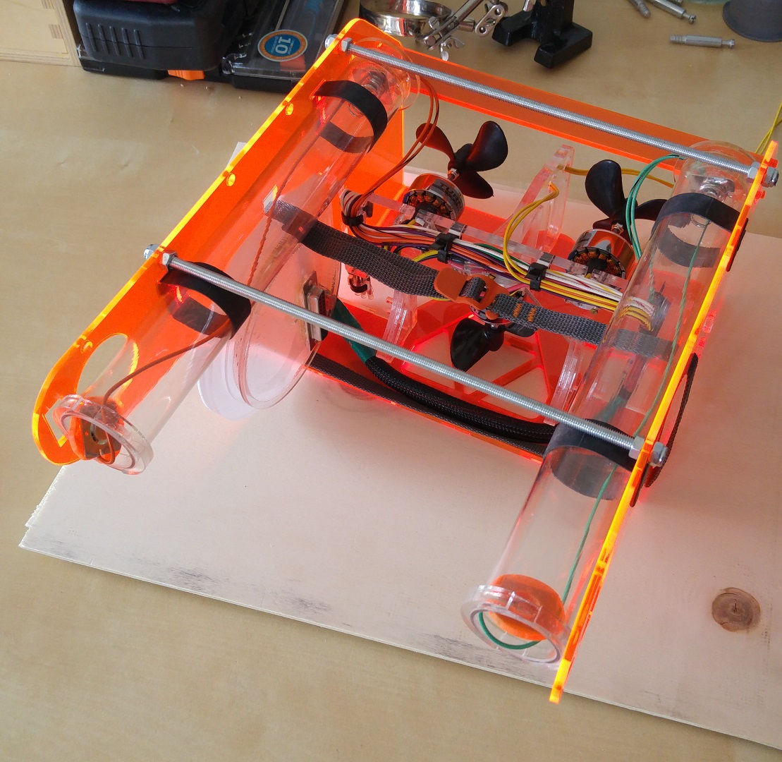
ROV hardware construction
The ESCs I used are "Afro ESC 12Amp OPTO UltraLite Multirotor ESC V3" from Hobbyking, and the same reccomended by OpenROV. One thing I had neglected was that the Afro ESCs needed to be programmed for reverse mode before being used. To do this, one needs a Turnigy one-wire USB interface. However, a clever individual has made an Arduino one-wire interface, which can be used instead. Flashing the correct firmware on the ESC is then simply a matter of connecting the ESC to the Arduino as described on the GitHub page. Avrdude can then be used through the Arduino virtual serial port, to program the ESC. This is the avrdude command I used, for reference:
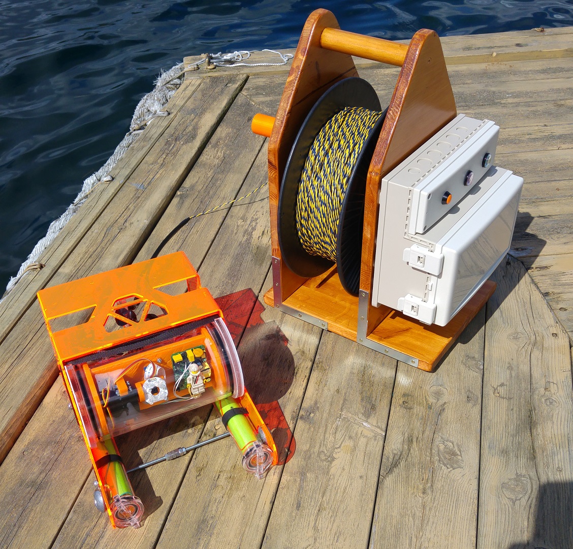
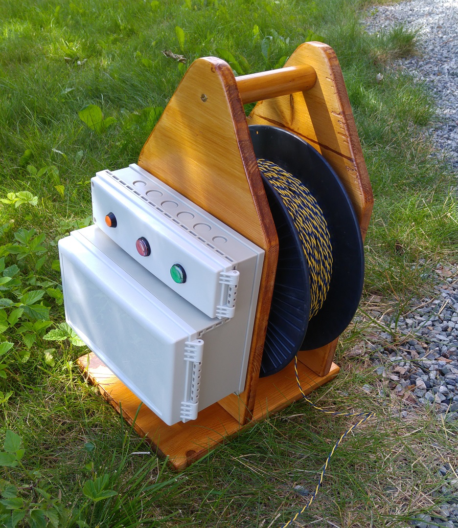
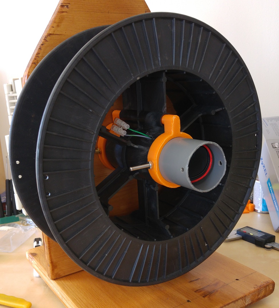
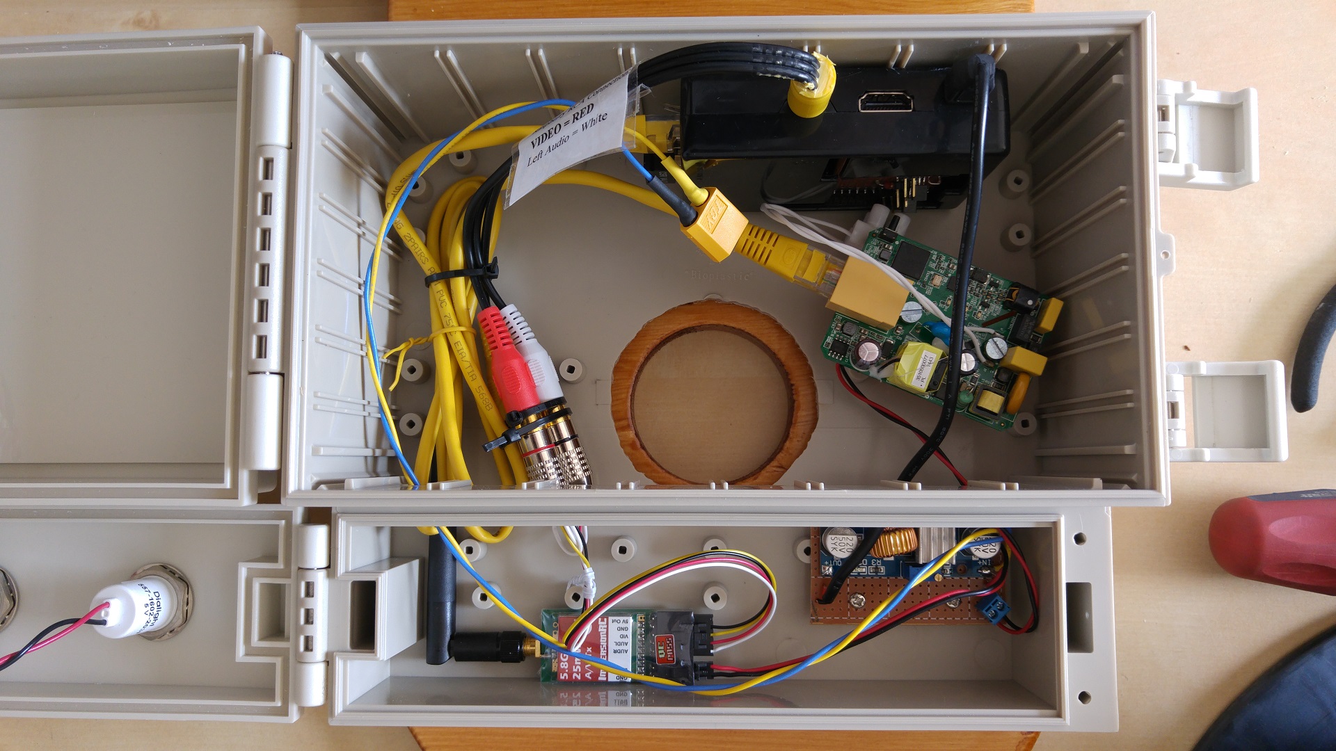
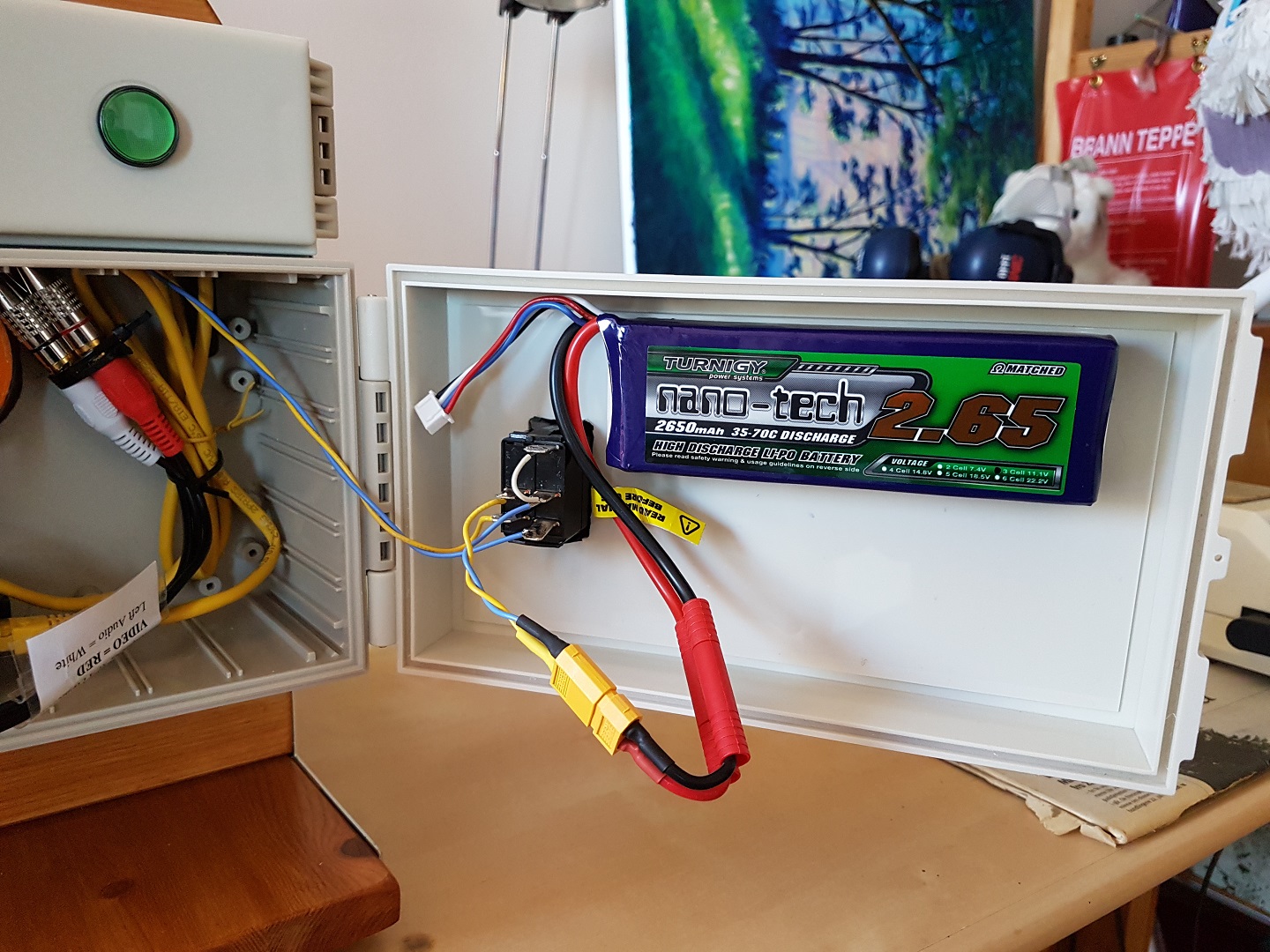
Once the ROV was constructed, I began work on the tether reel. An important goal for this project was ease of use, so the only user interface I wanted was a PS3 joystick, and a pair of standard FPV goggles. These are both wireless which make it easy to water-proof the tether assembly, and not having the operator cabled to the tether is very practical in a small boat. As with my previous ROV tethers I used a slip ring, so the tether can be coiled up and hopefully avoid tangles. An electronics box from AliExpress was used to house all of the tether electronics, which consist of a Raspberry Pi, Lipo battery, Ethernet interface, 5.8GHz FPV video transmitter, and voltage regulator. Two LEDs, and a power switch are the only external interaction points on the tether. Green for connection status, red for recording, and the button to safely shut down the raspberry pi in the tether, which at the same time sends a shutdown signal to the ROV.
To control the ROV and tether, I use a Raspberry Pi 2 running Raspbian Jessie Lite in each unit. All control scripts are started at boot time, ensuring no configuration is needed in the field. One raspberry pi in the ROV simply streams live video, using the Raspberry Pi camera, while at the same time listening for control packets. The control packets dictate how to control the ROV thrusters, LEDs, camera pitch, and also whether to start/stop recording. The tether Raspberry Pi attempts to connect to a Playstation 3 controller over bluetooth, and also connect to the ROV over Ethernet. Once both connections are established, the live video feed from the ROV is sent out to the goggles. Any changes in the PS3 controller state are translated into a control packet, which is sent down to the ROV. All functions on the ROV can be controlled via the PS3 controller.
Raspbian Setup
First of all setup Wifi, this is needed for installing various components, but also very useful for transferring files, and makes configuration changes. I copied files over SSH using WinSCP, and remote console using Putty. SSH is enabled by default in Raspbian Jessie.
In wpa_supplicant.conf I added a few wireless networks with Internet access, and also a "fake" network which I can use for debugging purposes in the field. This can be used by creating a local access point on my computer or smartphone, using the predefined SSID and password, if no router is available. I chose the following SSID and password.
SSID: "ROVDEBUG"
PSK: "UNDERTHESEA"
Since the two Raspberry Pi's communicate to each-other over Ethernet, they had to be set to have static IP addresses. This can be done by editing the file /etc/network/interfaces using any text editor.
	auto eth0
	allow-hotplug eth0
	iface eth0 inet static
	address 172.28.0.10	(for the topside module)	172.28.0.12	(for the subsea unit)
	netmask 255.240.0.0
Ethernet and wlan need to be on different network classes to work at the same time. Most routers use either 10.0.0.x or 192.168.1.x as their internal range, which is either network class A or C. I put the Ethernet of the pi's on class B (172.16.0.0) to avoid problems.
The final thing to setup is I2C for communication with the servo controller board. Run raspi-config, and enable I2C from the settings presented. To interface with the I2C controller with Python, additional support must be installed. Run these commands, and afterwards reboot.
Windows 10 Wifi access point (for debugging in the field)
I found it strangely difficult to set up a useful Wifi access point on my Windows 10 laptop. In addition to only being possible to set up through a command prompt, I also had to install some third party software to act as a DHCP server. To set up the network itself, open an administer privileged command prompt, and enter the commands:
To see the current status of the connection, or shut it down again, use these commands:
	netsh wlan show hostednetwork
	netsh wlan stop hostednetwork
Once started, the network will appear in under the network connections in the control panel. From here you should configure the connection to have a static IP address, so the DHCP server can interface with it. I used the following settings:
IP address: 192.168.1.1
Network Mask: 255.255.255.0
Default Gateway: Blank
Preferred DNS server: 127.0.0.1
Alternate DNS Server: Blank
For the DHCP server, I installed dhcpsrv. Simply run the program to automatically assign IP addresses to connecting devices. The ini file should contain the correct config, but if not, download the .ini file I used and change the directories to match your set up.
Video Streaming
An important requirement for this project was the ability to stream live video with very low latency, while at the same time being able to record it for storage. To this end I found that some people were having success using gstreamer. The idea was that the raspberry pi camera encodes raw video in h264 format at a hardware level, which means there is very little overhead required in software to send the video feed. To install gstreamer, run these commands:
I made some bash files to to control streaming and receiving of video. For the video transmitter I made two scripts, one for live feed, and one for live feed with storage to disk. Before starting each feed, I close any previous transmission which might be in progress using a pkill command. The first script simply pipelines the raw raspivid feed into gstreamer, whereas the second does the same, but at the same time splits the pipeline feed into a file for storage.
Live feed with no storage
	#!/bin/bash
	pkill -INT tee
	pkill -INT raspivid
	pkill -INT gst-launch-1.0

	# Wait for the process to clean up and terminate
	sleep 1

	raspivid -t 0 -w 1080 -h 720 -fps 25 -hf -vf -awb off -awbg 1.9,1.6 -drc high -b 2000000 -o - |
	gst-launch-1.0 -v fdsrc ! h264parse ! rtph264pay config-interval=1 pt=96 ! gdppay ! tcpserversink host=172.28.0.12 port=5000 &
Live feed with video storage
	#!/bin/bash
	pkill -INT tee
	pkill -INT raspivid
	pkill -INT gst-launch-1.0

	# Find an available file name
	STORAGE_DIR="/home/pi/capturedVideo/"
	mkdir -p $STORAGE_DIR

	# Wait for the dir to be created. Also wait for the process to clean up and terminate
	sleep 1

	fileIndex="0"
	fileName="rov_video"
	extension=".h264"
	fullFilePath=$STORAGE_DIR$fileName$fileIndex$extension

	while [ -f $STORAGE_DIR$fileName$fileIndex$extension ]
	do
		fileIndex=$[$fileIndex+1]
		fullFilePath=$STORAGE_DIR$fileName$fileIndex$extension
	done
	safeFileName=$fileName$fileIndex$extension

	echo $safeFileName

	# Start piping video into the chosen file!
	raspivid -t 0 -w 1080 -h 720 -fps 25 -hf -vf -awb off -awbg 1.9,1.6 -drc high -b 2000000 -o - |
	tee $STORAGE_DIR$safeFileName |
	gst-launch-1.0 -v fdsrc ! h264parse ! rtph264pay config-interval=1 pt=96 ! gdppay ! tcpserversink host=172.28.0.12 port=5000 &
Receiving video is equally simple. For that I use a script which continuously tries to connect to the ROVs static IP address and video port defined in the above scripts. Once a connection is made the video feed is displayed.
	#!/bin/bash

	until 1; do
	   gst-launch-1.0 -v tcpclientsrc host=172.28.0.12 port=5000 ! gdpdepay ! rtph264depay ! avdec_h264 ! videoconvert ! autovideosink sync=false
	   echo "Restarting process in 2 seconds..."
	   sleep 2
	done
If you have any problems streaming video, read these two pages. There may be some additional setup that is required.
For connecting a Playstation 3 controller (Sixaxis or Dualshock3) I used QtSixA. Installing and using this places the joystick in the system's native "/dev/input/js0" input. Raw data can be read using:
jstest /dev/input/js0
QtSixA is installed using "checkinstall". It also requires a number of dependencies. Run the following commands:
Once all installations are complete, run the command hciconfig. Something like this should appear, but if not, you have an unsupported bluetooth dongle.
I found a bug in QtSixA, where disconnecting a connected controller would cause a hang. I fixed the bug, and the corrected source code can be downloaded here.
uzzors2k - QtSixA.zip
Create a new directory, and extract the above files into it. Enter the directory, and run the commands:
	make
	sudo mkdir -p /var/lib/sixad/profiles
	sudo checkinstall
A controller must be paired before use, and it MUST be a genuine controller. Chinese rip-offs do not work, for some reason. Connect with a USB cable, and run "sudo ./sixpair" If pairing is successful, then the bluetooth master address should be changed to that of the PS3 controller.
	Current Bluetooth master: 00:00:00:00:00:00
	Setting master bd_addr to: 00:1F:81:00:06:20
Now to test everything, launch temporary a sixad daemon.
sudo sixad --start
Then press the "PS" button on the controller, and if everything works the controller should vibrate. To turn off the controller, press and hold the PS button for 12 seconds. To start the controller service automatically when booting the raspberry pi, run these commands:
	sudo update-rc.d sixad defaults
	reboot
After doing this it should simply be a matter of pressing the PS button whenever you want to use the controller. If a paired controller doesn't connect at start, run "hcitool dev". If no devices show up, then the bluetooth module failed to initialize. Need to reboot in that case.
Ethernet Communication and Servo Control
Servos are controlled using a Adafruit 16-Channel PWM/Servo HAT for Raspberry Pi. I wrote a number of scripts in Python for reading joystick signals from /dev/input/js0, receiving packets from the tether, and translating these to servo control signals. All of the code I used is hosted on github, under the project raspberrypi-openrov. I send TCP packets containing strings between the tether and ROV. These strings are in a set format, and interpreted by the ROV to control it's own outputs. The way I mapped the PS3 controller to the data in the packets is arbitrary, and can be configured to match most controllers. I've included code for a Nintendo Wii based controller also.
X defined as forward direction, Y as 90 degrees to this on the same plane, and Z as Upwards direction.
Each field below can be separated by a semicolon ';' when chained together in a single string/packet. Packets start with a '<' character and end with a '>' character.
	SET_VIDEO_RECORD:<0-1>
	SET_LIGHT:<0 to 512>

	ROTATE_ROV_YAW:<-512 to 512>

	TRANSLATE_ROV_X:<-512 to 512>
	TRANSLATE_ROV_Y:<-512 to 512>
	TRANSLATE_ROV_Z:<-512 to 512>

	ROTATE_CAMERA_YAW:<-512 to 512>
	ROTATE_CAMERA_PITCH:<-512 to 512>

	SYSTEM_SHUTDOWN:<0-1>
Closing thoughts
After testing the ROV at my cabin, I discovered numerous points of improvement.
Handle for the ROV, and GoPro connector
An on screen display would have been great to view battery time. Also some kind of gyroscope and compass sensor, to know what the current orientation is.
The LED lights illuminate the inside of the chamber. Need to place further out on the sides like in the original OpenROV, or upgrade to external lights.
ROV and equipment back-pack. As is I need to bring a lot of odds and ends with me, things like silicon grease, pliers, battery charger, etc.
Make a power switch like the original OpenROV, based on Ethernet connectivity. Having to open the ROV to turn it on and off became a hassle very quickly.
Connection start-up reliability. Sometimes the bluetooth module in the tether failed to start, and a restart was required. I tried some auto-reboot scripts, but these weren't reliable either. I need to investigate other dongles, or perhaps upgrade to the the Raspberry Pi 3.
Set the camera focus carefully.
I forgot to put an external power switch on tether! The switch currently on it only sends a shutdown signal to the ROVs, but does not kill the power to the tether.
My user experience was:
Hard to get going, worst is the power switch for the ROV inside of the main housing.
Bluetooth doesn't always work, requiring a tether restart. This is tedious, and sometimes requires a the ROV to be reset also.
I hope to revisit this project and improve upon these points for next time!
Update - 09.09.2017
During the past year I incorporated a number of fixes on the problems I had experienced after the first expeditions. Here's the list:
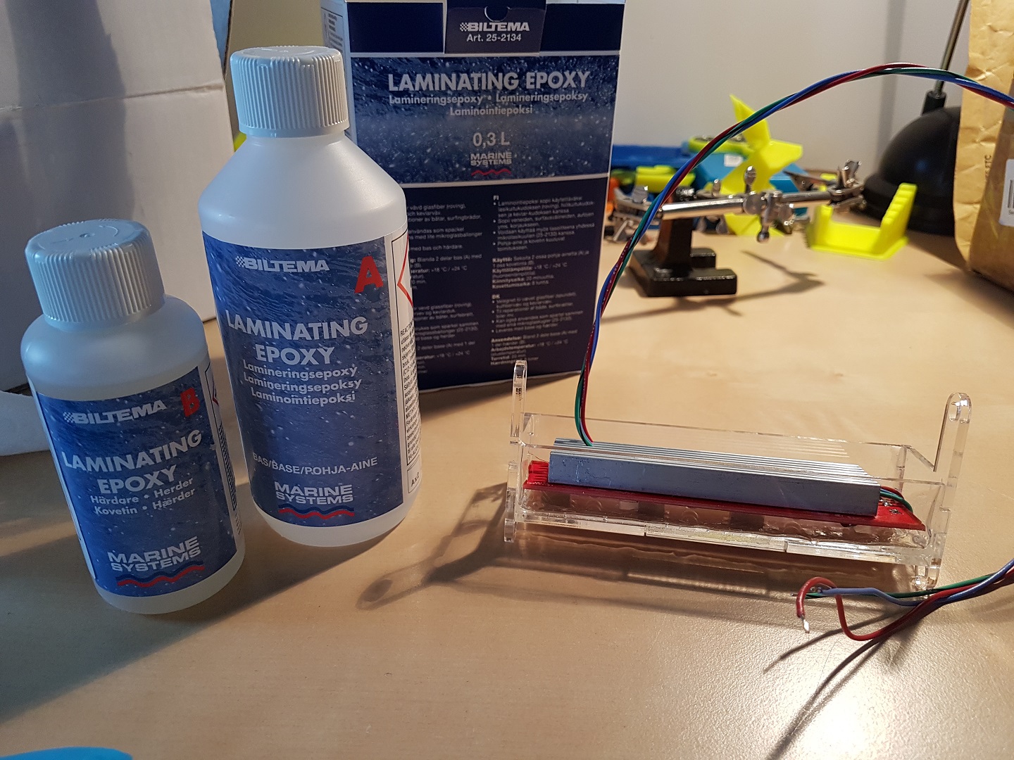
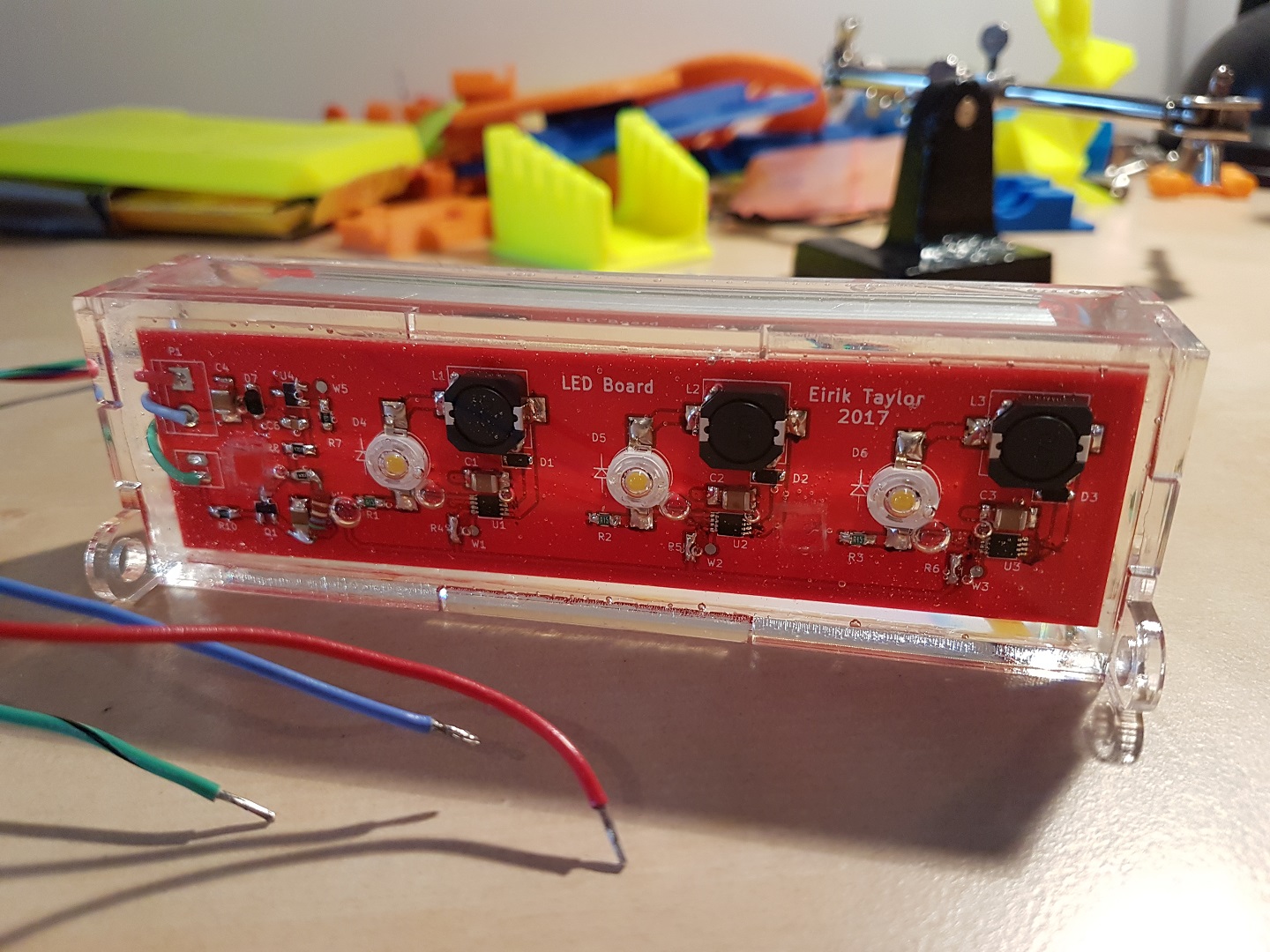
Built an external LED module with PWM regulation, and attached to the ROV.
Put a waterproof power switch on the tether, and velcro strap for holding the battery in place.
Tuned the raspberry pi camera focal point. Removed the read power LED to remove glare.
Tested a hall effect power switch which worked, however the mosfet overheated and died. Will need further development.
Made an equipment backpack. Contains everything to get the ROV running, and to perform field repairs or maintenance. This really reduced the threshold for bringing it out for an expedition.
Velcro battery holder, and power switch for the tether. External LED module for ROV.
This time I used a GoPro Hero 2 to record video, instead of the on-board raspberry pi camera. This greatly improved video quality, making me wonder why on earth I didn't do it for my earlier ROVs!
Disclaimer:
I do not take responsibility for any injury, death, hurt ego, or other
forms of personal damage which may result from recreating these
experiments. Projects are merely presented as a source of inspiration,
and should only be conducted by responsible individuals, or under the
supervision of responsible individuals. It is your own life, so proceed
at your own risk! All projects are for noncommercial use only.


 This work is licensed under a
Creative Commons Attribution-Noncommercial-Share Alike 3.0 Unported License.
This work is licensed under a
Creative Commons Attribution-Noncommercial-Share Alike 3.0 Unported License.