
Low Voltage Bench supply from a MOT (Microwave oven transformer)
Getting a proper bench supply is necessary for any hobbyist, and can often be a limiting factor when experimenting. Buying a high tech bench supply is very expensive, and buying a bench supply which can handle some real power is even more expensive. More often than not a crude, simple, industrucable power supply is what's truly required, and for this application nothing beats a good old iron beast. MOTs (Microwave oven transformers) are readily available, rated for around 1 kW, and easy to rewind.
Quick and dirty version
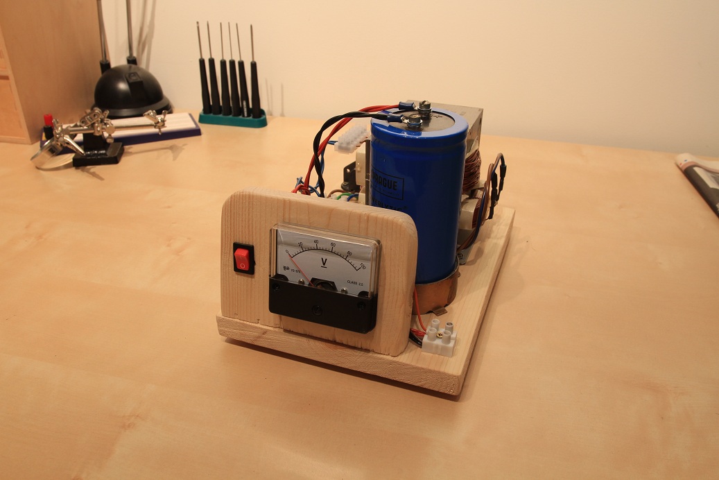
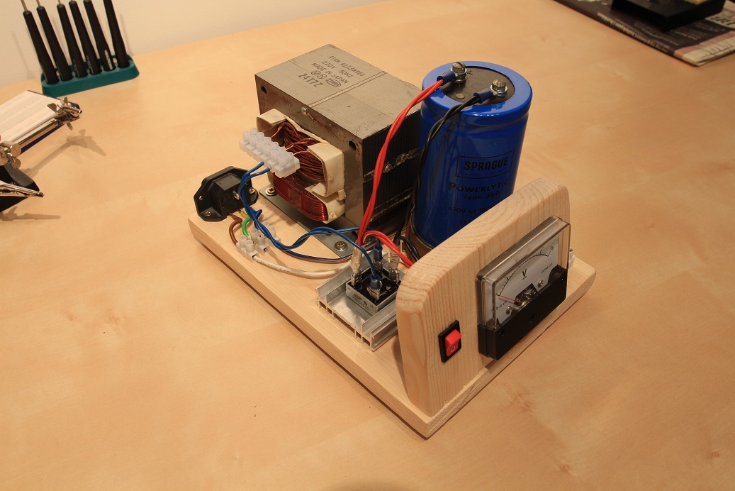
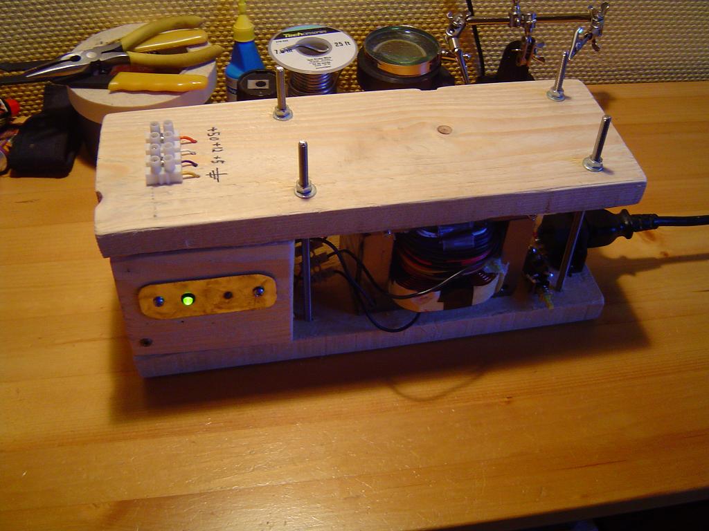
The first supply presented here is actually the most recently built one, being just a little weekend project. Still, I think it outperforms any supply I've built so far, simply by virtue of being so simple and versatile. It's also much better constructed than the second supply. The idea here is to rewind a transformer with several voltage taps, and then provide a rectification and filtration circuit. Optionally a voltmeter can be added as well. This way a number of voltages can be selected, simply by choosing which tap to rectify. With a voltmeter built into the supply, you'll always know what the voltage is, even as it sags with load. This is a feature I missed sorely on the supply below. The electrical circuit is so simple I haven't drawn it, but if you need to see it just look here for the equivalent.
Short Circuit Protected Version
Of course, simply winding and rectifying a monster transformer is not always such a good idea, as all it takes is one failure and everything down the line is ruined. This can be remedied by using some simple protection circuitry. The short circuit protection was designed by Tim Williams. I added a few changes, but nothing worth mentioning. It’s a discrete flip flop which switches the power MOSFET off when a short occurs, and closes it when the reset button is pushed. Pretty self-explanatory and simple, but it will save you a lot of work in the event of a load failure. A neat bi-color LED will switch between green when everything is OK and red when a short is present. An overcurrent condition is detected by measuring the voltage across a resistor as mentioned earlier. Once this voltage exceeds the base threshold of a 2N3904 transistor the flip-flop is triggered, and will remain on until reset manually. In the set condition, the main power mosfet is opened, which prevents current flow to ground. This in turn "shuts off the power" to any circuit down stream, preventing further damage. Keep in mind that current may still flow from the 50V line to 12V or 5V

By using two separate windings and a little extra circuitry, the supply is able to give a regulated +5 and +12 volts and an unregulated 50 volt line. Depending on the components used, the 50 volt line can supply up to a kilowatt! Not bad for something homemade. Remember that this supply is not protected from a short between +50V and the regulated +5V and +12V lines. The overcurrent level is decided by the 0.024 ohm resistor, which will develop a 0.6 voltage difference from real ground when 25 amps pass through it. The size of the current sense resistor is determined by the transistor turn on voltage divided by the max current, so just Ohm’s law. In this case,
0.6V / 25A = 0.024 ohms
With only one 0.047 ohm resistor the peak current allowed is;
0.6V / 0.047 = 12.7 A

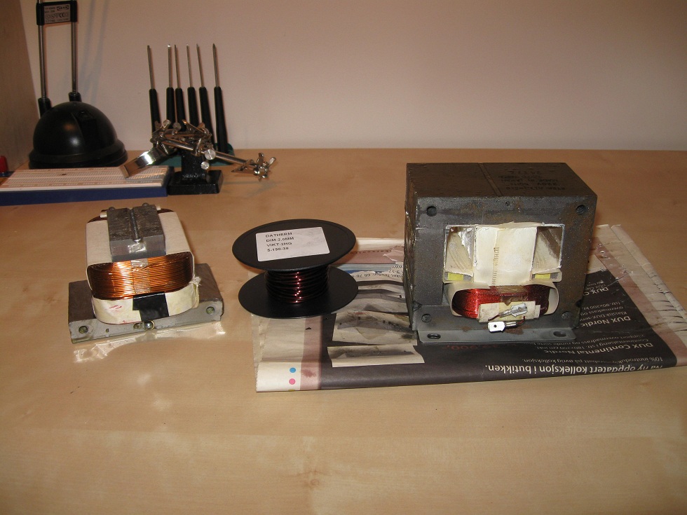
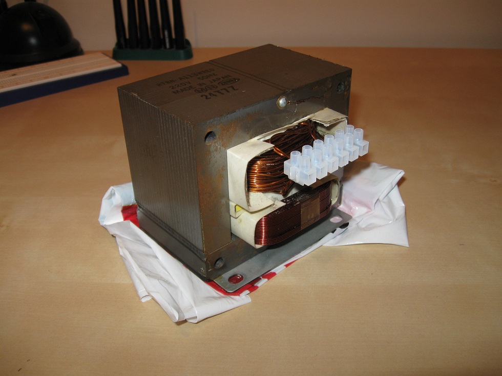
Rewinding the MOT
The MOT is the heart of the power supply. They are often welded shut, and must be cut open with an angle grinder to be rewound. Once you have ground the welds down, it will still be glued together with varnish. Give the “I” section a knock with a hammer and will break it off. Be sure to hit the laminations sideways, my Dad and I learned the hard way. Once the top section is off, remove the secondary winding however you like, but be very careful with the primary winding – you will need it later. Once the transformer is disassembled, it is time to wind. Pick a wire size which will allow for 50 turns, and if possible use enameled wire, not plastic coated. I used 18 AWG plastic coated wire, which is all I had at the time. If you want to achieve a specific output voltage, wind a few turns, measure the voltage, then divide by the number of turns. Keep in mind that the output voltage per turn decreases as you add more turns to the core. Outer turns may only generate 80% of the voltage you'd get from an inner turn.
For this particular supply you're aiming for 13V AC on the low voltage line and 35V AC on the 50V line. Once you are ready to test the transformer, it is necessary to clamp it tightly, otherwise the mains buzz will shake your bench apart. Welding the transformer shut again would not be a bad idea.
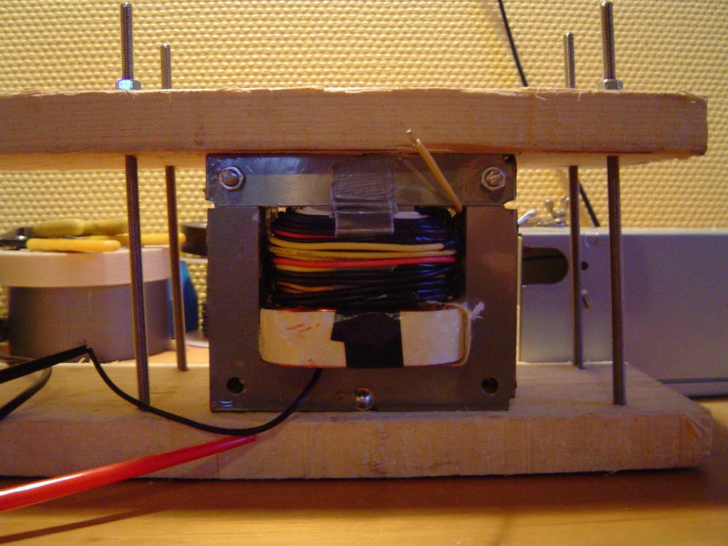
No, I didn't use one piece of wire.
![]()
![]()
![]()
![]()
Disclaimer: I do not take responsibility for any injury, death, hurt ego, or other forms of personal damage which may result from recreating these experiments. Projects are merely presented as a source of inspiration, and should only be conducted by responsible individuals, or under the supervision of responsible individuals. It is your own life, so proceed at your own risk! All projects are for noncommercial use only.
 This work is licensed under a
Creative Commons Attribution-Noncommercial-Share Alike 3.0 Unported License.
This work is licensed under a
Creative Commons Attribution-Noncommercial-Share Alike 3.0 Unported License.
4545 unique visitors since 28th June 2020.