Inductors, capacitors and alternating current. All related, and a part
of the mysterious imaginary side of electronics. The reason I built yet
another microcontroller based meter for measuring reactive components
is the poor range mostmeters on the Internet have. Up until
now
I have used the classic PIC16F84 L/C Meter. While the inductance range
was good, it could only measure capacitors up to 100nF, and lacked a
frequency measuring option. So for a "weekend" project I decided to
improve upon the design and create my own L/C/F meter with all the
function and range I desired, using the well known ATmega8515 that
comes default with the STK500 board. One month later I can now gift the
Internet with yet another L/C/F Meter.
I started by making a RC capacitance
meter, which measures capacitance by taking the time it takes a
capacitor to reach 0,63% of full charge. This time is equal to one time
constant, and the math required to find the capacitance is just C = Tau
/ R. With a regulated 5,00V source, the capacitor voltage will have
reached 3,16V after one time constant. The internal comparator in the
ATmega8515 will trigger an interrupt once this voltage has been
reached. The 2N3904 just drains the test capacitor, while the two
2N3906s
are used to select a resistor depending on the measuring range. The
critical components here are the 470 and 39k resistors, hence the 1% or
better tolerance rating. The L/C portion of the circuit is just like
all of the other classic L/C meters out there. A LM311 is used as a
neat little LC oscillator with a switch to swap between putting a test
capacitor in parallel with the reference capacitor, or a test inductor
in series with the reference inductor. The only critical component here
is the 1,00nF reference capacitor, which should have a tolerance of 1%
or
better. The reference inductor only needs to be in the range of
50-100µH. The output from the LM311 is a square-wave who's
frequency
depends on the L/C combination, and the deviance in this frequency is
used to determine the inductance or capacitance of the tested
component. Whether measuring capacitance or inductance, the circuit is
set-up so the component being measured is lumped together with the
reference component, which simplifies the calculations required. None
the less, some pretty advanced math is required considering the built
in math capabilities of the AVR, which makes me glad C compliers with
floating point support exist!
See this site if you want to make awesome looking formula!
As is evident from the formula, certain references are established,
namely f1 which is the initial resonant frequency of the meter and L1
which is the size of the reference inductor. These are determined at
program start-up and stored for later use. Since the meter needs to
measure frequency for the L/C portion anyway,
it only takes another switch and some input protection circuitry to
make a frequency counter. The counter simply increments with each
rising edge, and after one second the count equals the frequency in
Hertz. As such the frequency counter has a resolution of 1Hz. For this
project I started using WinAVR
which is based on the avr-gcc, or maybe it's the same thing. It's open
source and based on standard C at any rate, so hopefully my code will
be more useful and portable than previous projects which have used
evaluation versions of MikroC or basic. I've commented the code as I
went, hopefully it's readable and intuitive. I've added an in depth
explanation of how the code works in the comments, so check out the
source
code here if you're interested: lcf_meter.c
The LCD library I used was created by Peter Fleury,
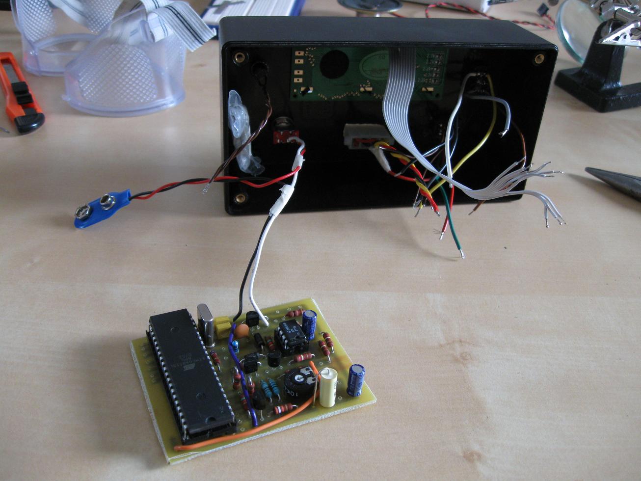
thanks a bunch Peter. I've made a PCB for this project,
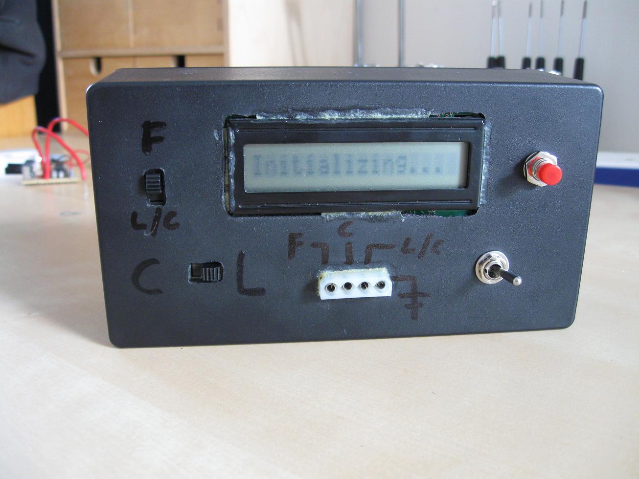
mainly because I can't be bothered working with veroboard anymore. The PCB files, source code, hex,
schematics, and whatever else I thought you might need are zipped in
this archive: LCF Meter Files.zip
Enjoy. One note on the PCB, two wires are needed.
One from ground to the top trace for the 2N3904, and one from 5V to Vcc on
the ATmega8515. Both are critical, so don't forget them! You can see
where they go on the PCB file, or on the PCB layout image in the PCB
folder, or below:
Between the numeric error in the floating point calculations, and the
reference capacitor being off by some minuscule amount, the total error
with the L/C meter
only seems to be a little over 1,0% on capacitors between 1nF and 50nF.
This has been confirmed with the finished prototype and various 1% to
0,3% tolerance capacitors. I don't have any high tolerance inductors to
test, nor capacitors over 50nF, so the other metering ranges haven't
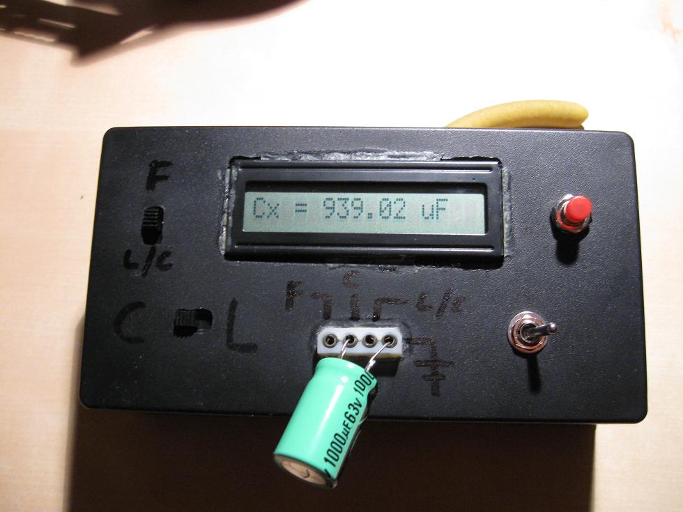
been empirically tested. The RC measuring range is primarily for 50nF
and up to 30mF (yes, milli as in 30000µF), where high accuracy
shouldn't be a primary concern anyway (who's ever heard of a high
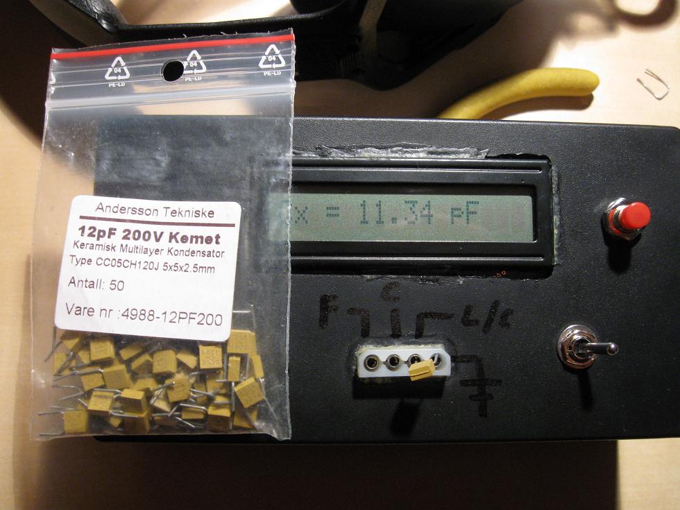
tolerance electrolytic?). The L/C range worked with
capacitors up to 1000nF on my breadboard, but this decreased to 300nF
once I boxed the project up, due to the error ramping up with
larger capacitors. I suspect the long internal test
leads may be the problem. Keep this in mind if you want the more
accurate L/C range for larger capacitors. Of course, the RC measuring
mode doesn't have this problem, and is quite accurate as well. It gave
me a reading of 49,86nF on
the50nF test capacitor. Keep in mind the tolerance of this
capacitor is 0,3% so the "error" of 0,28% read by the meter might be
spot on!
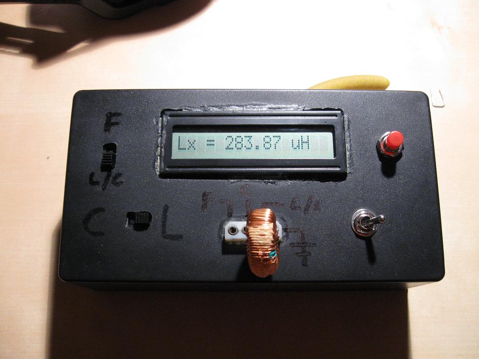
And of course, some photos of stuff being measured:
25.02.10
Update: I've been working with radio circuits lately and was a bit
disappointed with the nH range my meter provides. Or lack of nH range.
So I fixed the firmware to use a nH range as well as the µH and
mH. I've also put an over range detection in place for the LC
capacitance section. Firmware for 16x1 Char LCD can be downloaded here:
Updated_Firmware_LCFmeter.zip
I'm not completely satisfied yet however, since the minimum resolution
of the inductance meter seems to be 10nH, and even this figure swings a
lot. Preferably it should be 0,1nH in order to get decent measurements.
I've looked at the project again and determined that the only way to
increase resolution here would be to increase the reference frequency.
Currently it resides around 500-600kHz, which is at the maximun for the
LM311, but far from the 3,8MHz the ATmega8515 can measure. For any
daring souls wishing to make an even better LCF meter, use a high speed
comparator or something so the oscillator can run at a much higher
frequency. If you do, let me know! This shouldn't require firmware
changes.
Disclaimer:
I do not take responsibility for any injury, death, hurt ego, or other
forms of personal damage which may result from recreating these
experiments. Projects are merely presented as a source of inspiration,
and should only be conducted by responsible individuals, or under the
supervision of responsible individuals. It is your own life, so proceed
at your own risk! All projects are for noncommercial use only.

 This work is licensed under a
Creative Commons Attribution-Noncommercial-Share Alike 3.0 Unported License.
This work is licensed under a
Creative Commons Attribution-Noncommercial-Share Alike 3.0 Unported License.