Having played with a manually tuned induction heater a few times before
I knew how tedious it could be to operate. For one thing the resonant
frequency isn't constant, but varies with the work piece size and
temperature of the tank components. If the operating frequency is used
to regulate power, more time is spent watching a scope then the work
piece. What I wanted was a driver that would automatically find the
resonant frequency or regulate power on the fly. It would be nothing
new actually, as this type of driver has been done before only with
discretes (see links below). Tim William's IH is complicated
as hell though, and I wasn't going for something that elaborate. So after
many different versions I eventually got something which worked and was
reasonably simple.
The frequency control voltage appears at pin 9 which is the VCO
input. An analog OR gate (the diodes) is used to allow the strongest
signal to take control of the frequency. When the circuit starts up the
"soft-start" circuit is in control, consisting of just a
capacitor/resistor voltage delay. This ensures that the frequency
starts at maximum where power draw is minimal, it also makes sure the
PLL starts on the right side of the tank's resonant frequency.
As Richie has detailed on his site the LCLR arrangement presents a
capacitive load below resonance and inductive above resonance, with
inductive reactance being the most forgiving for a square wave
inverter. Therefor an increase in supply current or tank voltage brings
the VCO frequency up. On either side of resonance the impedance of the
LCLR circuit increases, lowering current draw and resonant rise. With
low supply voltages or proper loads neither the tank voltage nor the
inverter current will need regulation, in which case the driver must
lock onto the exact resonant frequency of the LCLR circuit for max
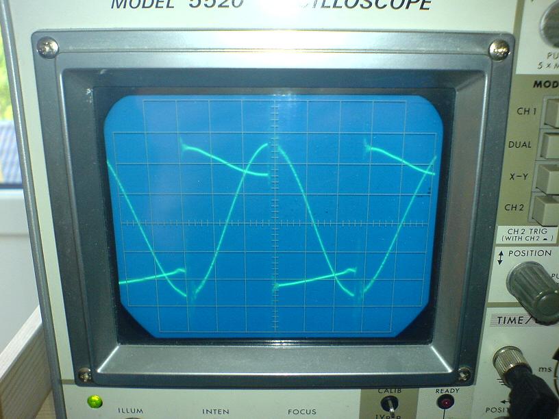
efficiency and power. The PLL takes care of this by adjusting the VCO
frequency to the point where the inverter output and tank voltage are
90 degrees out of phase (inverter leading the tank voltage), because
this phase difference characterizes resonance in a LCLR circuit. See
Richie Burnett's excellent article on the
LCLR topology
for more. The 4046 will lock two phases at 90
degrees difference by default, which is practical
for this usage. The tank and inverter voltage is sampled directly with
a 393 comparator thanks to the circuit's common ground. The single
discrete transistor inverter adds an additional 180 degree shift to the tank
voltage signal. Without the additional shift the internal XOR gate in
the 4046 was unable to detect the phase difference properly and would
lock somewhere below resonance.
Note: I haven't tried series resonant topology with this circuit,
but it should work too. Drop me an email if you try it and it
works so this can be confirmed!
If the load is too light allowing for greater tank Q, the voltage or
current will rise uncontrollably. Since both the voltage and current
sensors are similar I'll describe them as one. The desired signal is
detected and sent through a low pass filter giving a more or less
stable DC control signal. This signal is compared to the variable
reference created by the voltage divider and if too great triggers an
error. The error signal passes through the OR gate and takes control of
the VCO, regulating the voltage or current to an acceptable value. To
ease adjusting the potentiometers for different ranges I've made and
Excel spreadsheet
with various calculators available for download.
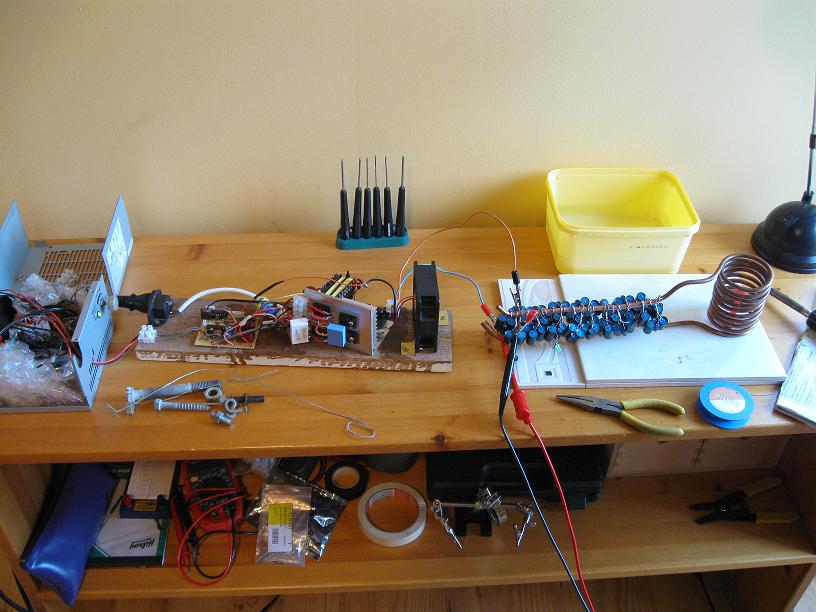
The actual power section of the circuit consists of doubled up
IRFP450s, powered from fullwave rectified mains. The size of my
matching inductor is 45μH, with a 1.7μF tank capacitor and
2.50μH work coil.
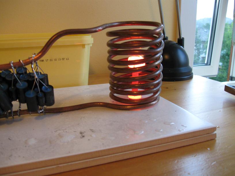
To test my new driver I had a large work coil and tank capacitor
already built for a previous induction heater project. The tank
capacitor was made up of 50x 22nF and 50x 12nF mini
capacitors I purchased cheaply off ebay, giving a total of 1.7μF at 600V.
So far I've had 3 capacitor failures, all of them with the small 12nF
ones. Other than that the bank has held up well and doesn't seem very
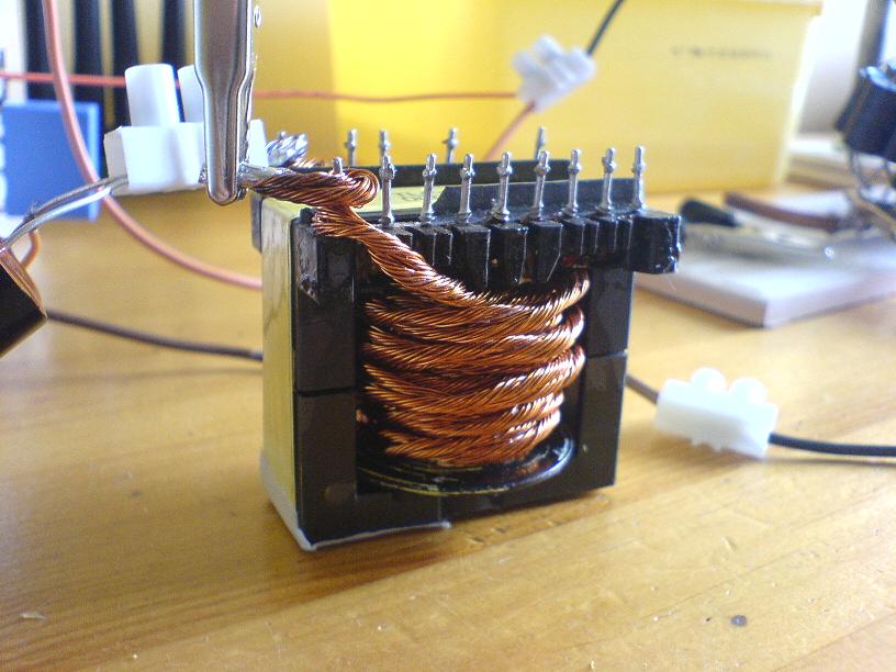
lossy. The most difficult component to construct was the matching
inductor, which dissipates surprising amounts of power due to the large
current flow. After a few failed attempts I had to use 32
strands of insulated 0.3mm magnet wire, wrapped together as litz wire. Even
with just 8.6 milli-Ohms of DC resistance I still had to use a fan to keep the
inductor temperature low enough. The reason litz wire is used over a
solid conductor is due to the Skin effect, which has to due with
current flow at high frequencies. As the frequency of the current
increases, more of the electrons will travel in the outer layer of a
conductor, increasing the apparent resistance of the conductor, because
the current flowing portion of the conductor becomes smaller. By
checking the skin depth of copper at various frequencies one can see
that at 100kHz, single strand copper wire with a radius over 0.2mm is
just excessive. (So by rights, I should have used 0.4mm wire instead
for optimal conduction)
Despite doubled up IRFP450s I couldn't seem to push more than 20A
through the inverter without the mosfets failing. The low inverter
current limits the power my induction heater can supply which is a bit
sad, since it can run nearly indefinitely as is meaning I'm no where
near pushing the limits of anything but the IRFP450s (even they run
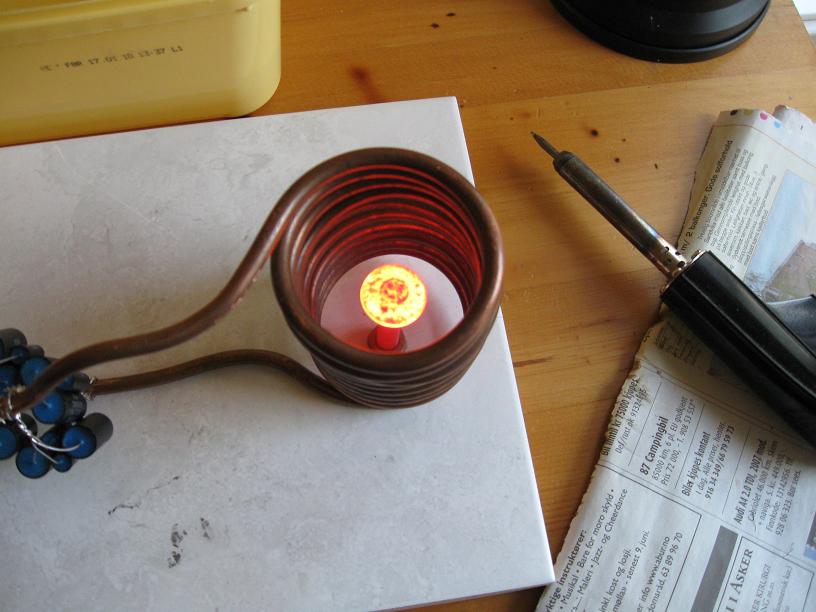
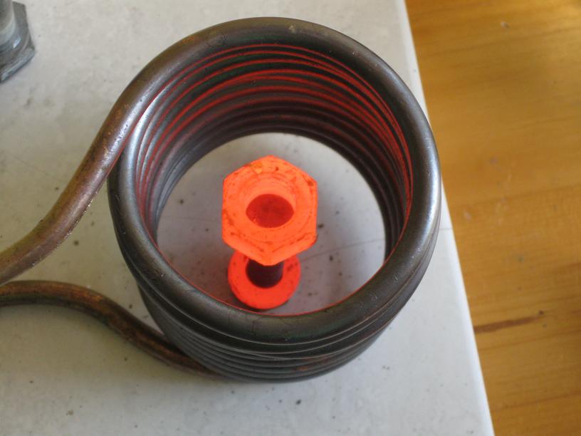
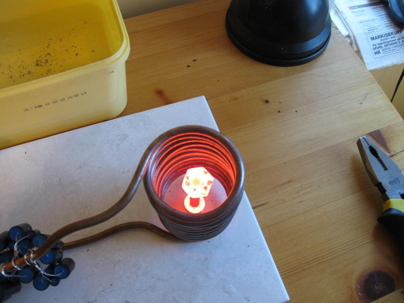
cool when the current is kept around 18A) yet. At least I was able to
heat objects quicker and to higher temperatures than my previous heater
could.
And finally thanks to Richie Burnett and Tim Williams for guiding advice on this project!
Youtube Video
Disclaimer:
I do not take responsibility for any injury, death, hurt ego, or other
forms of personal damage which may result from recreating these
experiments. Projects are merely presented as a source of inspiration,
and should only be conducted by responsible individuals, or under the
supervision of responsible individuals. It is your own life, so proceed
at your own risk! All projects are for noncommercial use only.

 This work is licensed under a
Creative Commons Attribution-Noncommercial-Share Alike 3.0 Unported License.
This work is licensed under a
Creative Commons Attribution-Noncommercial-Share Alike 3.0 Unported License.