While visiting my grandparents I found some old tubes in a box which
used to belong to my grandfather. Apparently they were part of an old
"Radionette" radio, which is now long gone. Having no prior experience
with tubes other than a VFD display, I thought it would be pretty cool
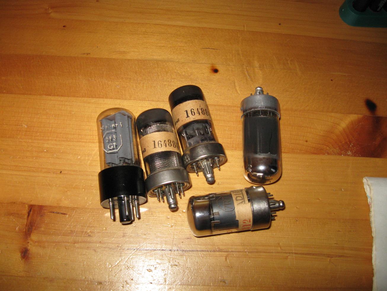
to recycle the tubes by using them in an audio amplifier. The tubes I
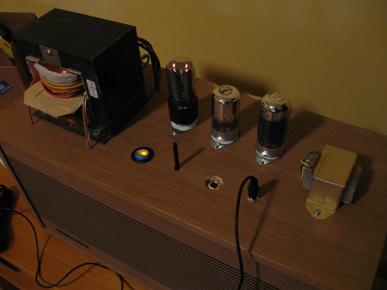
found were 5Y3GT, 7C5, 7R7, ECH21 and an unknown tube which was never
identified. After some research I found the 5Y3GT is a full-wave
rectifier and the 7C5 is a decent beam amplifier. I would have used the
7R7 as a pre-amp, but I later discovered the filament was out of order.
Since sockets had been purchased and installed in the loudspeaker
cabinet at this point I bought a NOS 7B6 on ebay to replace the 7R7.
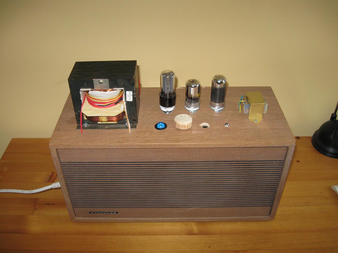
During my dumpster-diving adventures some summers ago I found a good
many speakers, which I still have stashed in a closet. A 4-ohm, brown,
70's speaker caught my eye and was chosen to be the cabinet for this
project. When first using tubes I might as well get rid of anything
else that's old. The only only real setback remaining was finding the
required transformers. The power transformer required a center-tapped
400V output, a 6.3V filament, and 5V filament. On top of that tube amps
require impedance matching, which is easiest done with a transformer.
That adds up to a lot of expenses for something which was only meant as
a novelty. However I had a MOT with a shorted secondary, and a still
functioning primary. Not my first choice, MOTs run hot and noisy, but I
took it. As for the impedance matching transformer, the datasheet for
the 7C5 (output tube) specifies a plate load of 5k ohms. Since I'm
using a 4-ohm speaker that's a ratio of 1250:1, and an impedance ratio
of sqrt(1250):1 or 35:1. The output power of the 7C5 is 5W, roughly the
same as your standard wall-wart. The voltage I planned on using in my
amplifier was 250V, close to the 220V mains used here. A transformer
with 35:1 ratio would have an output voltage close to 9V peak, so I dug
through my junk box and eventually found a cell phone charger with a
transformer which seemed about right. That settled the transformer
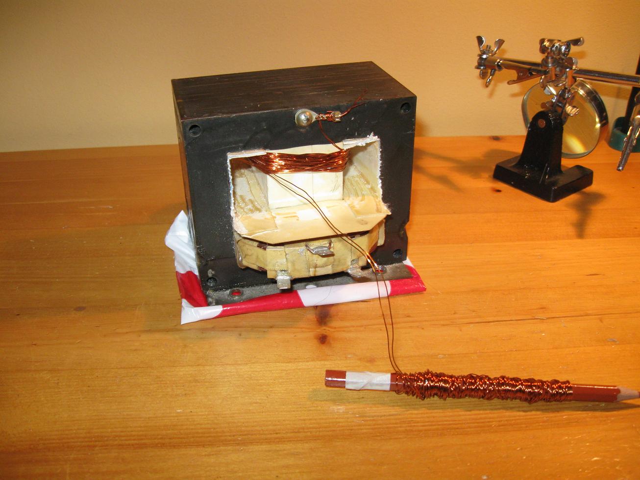
problems! When modifying the MOT I didn't want to cut it apart
otherwise the buzzing would make it useless (not that it's quiet
otherwise) for audio applications. To be able to wind a 200+200 turn
winding on a closed core I had to cut two 5 meter lengths of wire,
intertwine them, and wind them on a pencil. After a 5 meter length was
transferred to the core I repeated the process, and kept soldering the
two lengths together to get two continuous pieces. I hope the picture
and some intuition make this clear.
With the rare components secured I could start working out a circuit.
Basically I had to look at other designs and read about tubes until I
understood their basic functioning. With that done I checked out the
tube datasheets which provide sample circuits or simply show which
voltages need to be applied where. After stitching some of the images
together I had my design. :-) I found the tube datasheets at either; Radiomuseum.org,
NJ7P
Tube Database or The
National
Valve Museum.
The transformer voltages are AC values. Tubes are wonderfully simple to
use once you get to know them. The DC
voltage is supplied by a dual diode, the 5Y3GT, and filtered by an RC
network. Hardly efficient, but I wanted to use all tubes in this
amplifier so the near 100V volt drop from the transformer output to B+
(the 250V line) is just something I'll need to put up with. Compare
that with the 0.6V drop of a silicon rectifier! The 5Y3GT can only
support a limited filter capacitor size, so don't try putting too much
before the filter resistor (680R). There's not much that
can be said about this amplifier that is unique from any other tube design
out there. If parts of the schematic are unclear read about tube
amplifiers on the net. This page discusses triode amplifiers
(which can be applied to the pentode, 7C5, as well) and this one the output
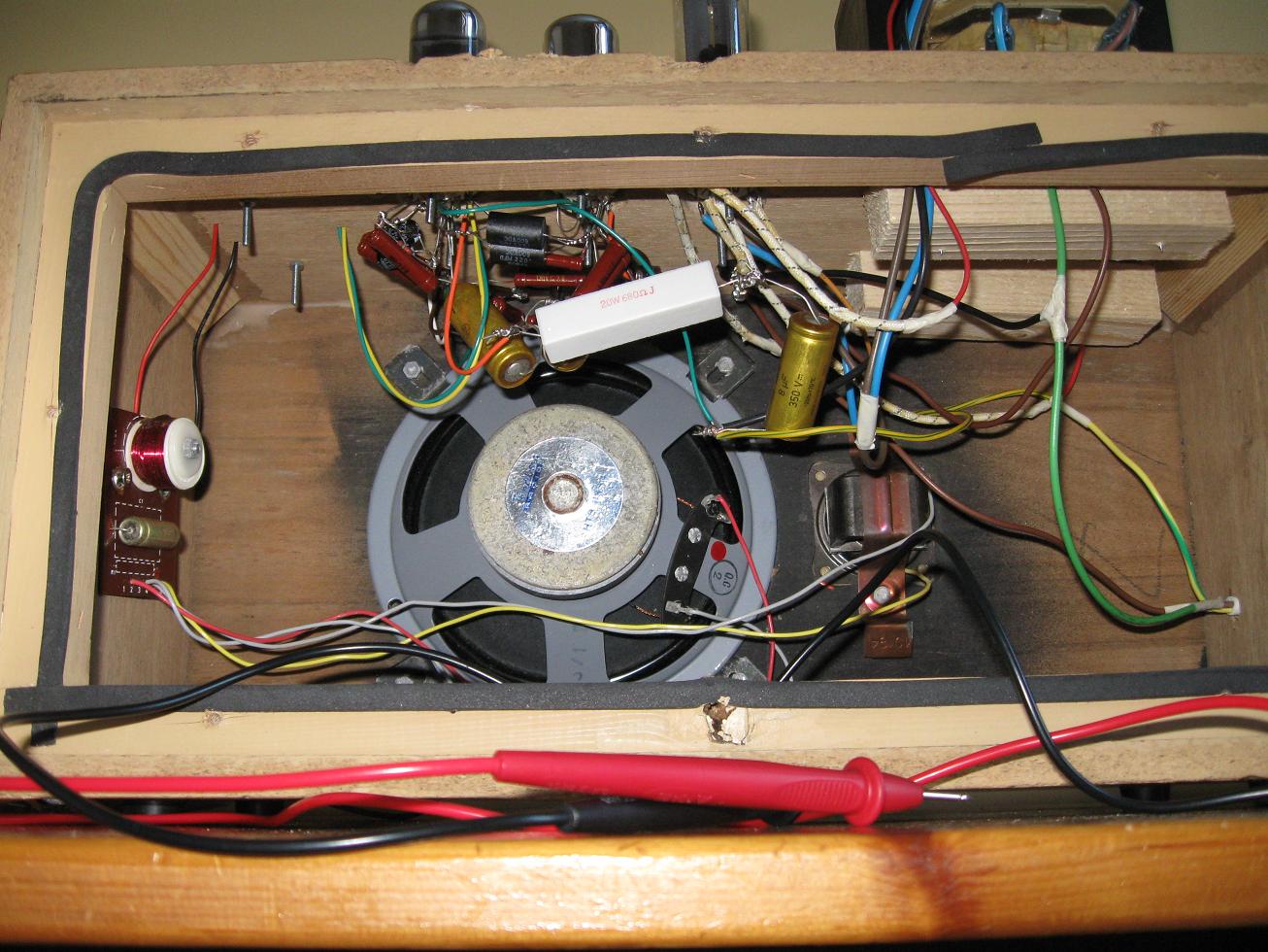
transformer. In the picture
below you can see i even used ancient resistors and capacitors. True
vintage sound! I'll admit there's a lot of humming, but remember that
nothing has been
optimized for fidelity, and there are plenty of things I could have
done differently to attenuate humming. Using modern silicon diodes to
provide 250V and larger filter capacitors would do wonders. Paying
better attention to the layout of the circuit would also improve signal
quality. Remember if you use silicon diodes and a proper filter, the
voltage drop will be much less so the transformer voltage can be 100V
lower. 180+180V would do nicely.
Disclaimer:
I do not take responsibility for any injury, death, hurt ego, or other
forms of personal damage which may result from recreating these
experiments. Projects are merely presented as a source of inspiration,
and should only be conducted by responsible individuals, or under the
supervision of responsible individuals. It is your own life, so proceed
at your own risk! All projects are for noncommercial use only.

 This work is licensed under a
Creative Commons Attribution-Noncommercial-Share Alike 3.0 Unported License.
This work is licensed under a
Creative Commons Attribution-Noncommercial-Share Alike 3.0 Unported License.