
DIY Stereo System
Ever want a great stereo system but know you are just better than buying one? If you are like me and have more time than money, it may worth looking into. Because building a stereo system isn’t as hard as it seems. Not that I’m so 1337 yet that I can make one out of tubes, so solid-state will have to do. (Only an audiophile can tell a difference in sound quality anyway)
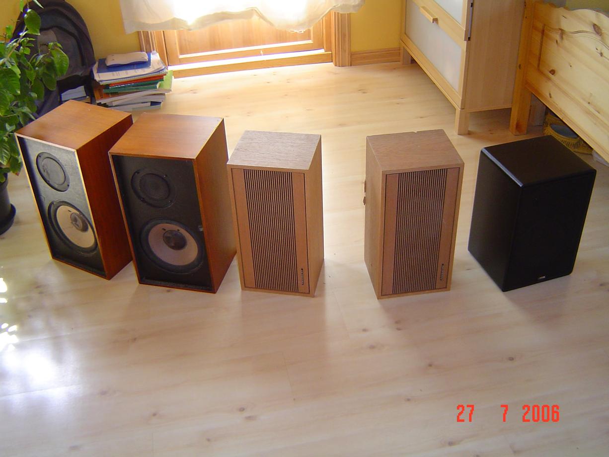
First you have to find 3 loudspeakers, two 8 ohms and preferably a 4 ohm one, but another 8 ohm will do. The two 8-ohm speakers are for the left and right channels and the 4 ohm is for the optional subwoofer. To stay within my budget I went to the dump and found 5 good loudspeakers. If you don’t have any luck at the dump try ebay or a pawn shop.
I’m assuming you know how to put a schematic together so build these. Remember to make two single channel amplifiers if you want stereo.
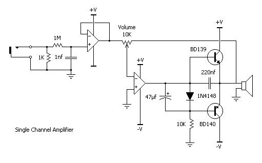
I used the TL-071CP operational amplifier, but a two-in-one or four-in-one package might be something to consider. I used two fixed value resistors instead of a volume potentiometer, since I didn't have a stereo audio pot available. That way both channels will always play just as loud. An audio pot with dual potentiometers inside is ideal though. You will notice significant distortion at high volume, so it’s a compromise between volume and sound quality. But this circuit is the best one I could find when it comes to heating, power usage and sound quality. I set the volume low on the circuit and turn it up loud on my computer, that way I get no audible distortion.
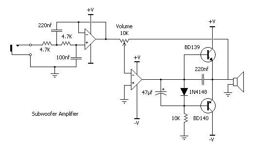
This amplifier is just like the channel amps, expect it autentates everything except bass. Us this >SPREADSHEET< to determine the cut-off frequency. Or use this formula;
1.4142 / (2*3.14*C1*R1)
The formula values are in Ohms and Farads. The 220nF cap is C1 and R1 is 2* the 4.7 resistors. The 100nF cap has to be half the size of C1 for the formula to be correct. If that's not clear just stick to the circuit, the cutoff frequency is 137 Hz which is about right.
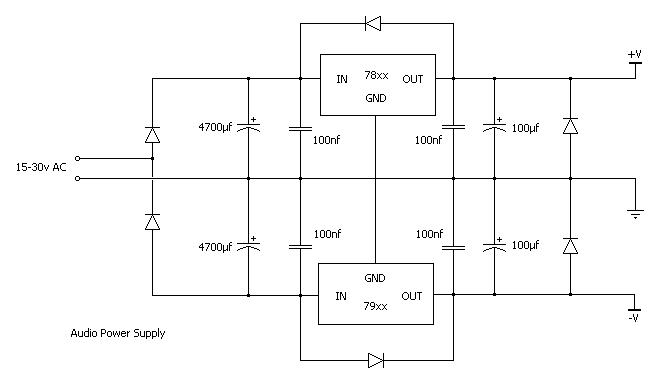
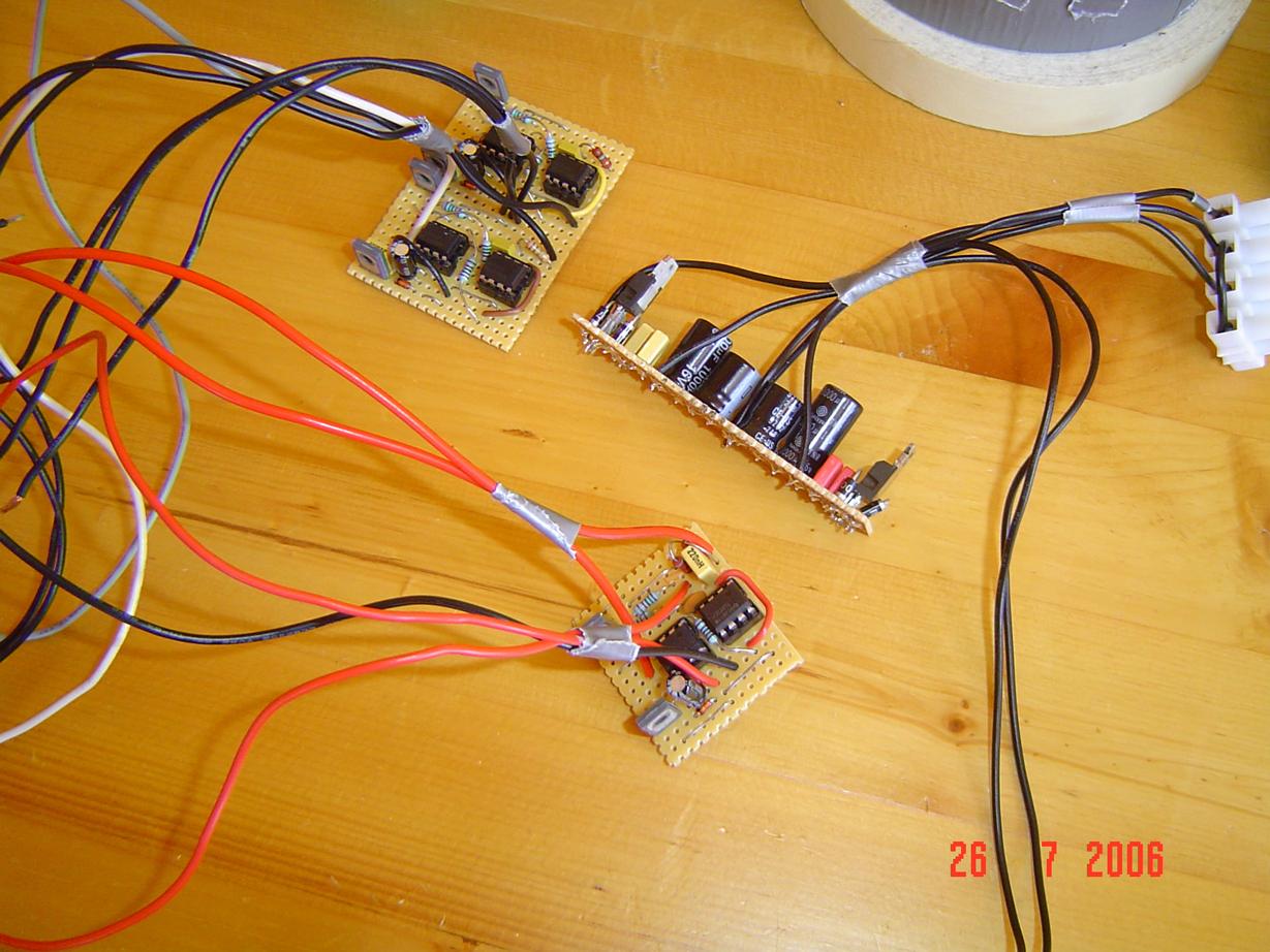
This is a type of voltage doubler which will give you a split rail power supply from an AC source. The 78xx and 79xx boxes are voltage regulators. The higher their voltage the more volume you’ll get out of the amplifier. Make sure they are a few volts under what your AC supply gives, and under the operating voltage of the op-amps you choose. Between 12 and 20 volts is a safe range. The xx part of the component name is the regulated output voltage.
Once you finish building those you should have something like this.
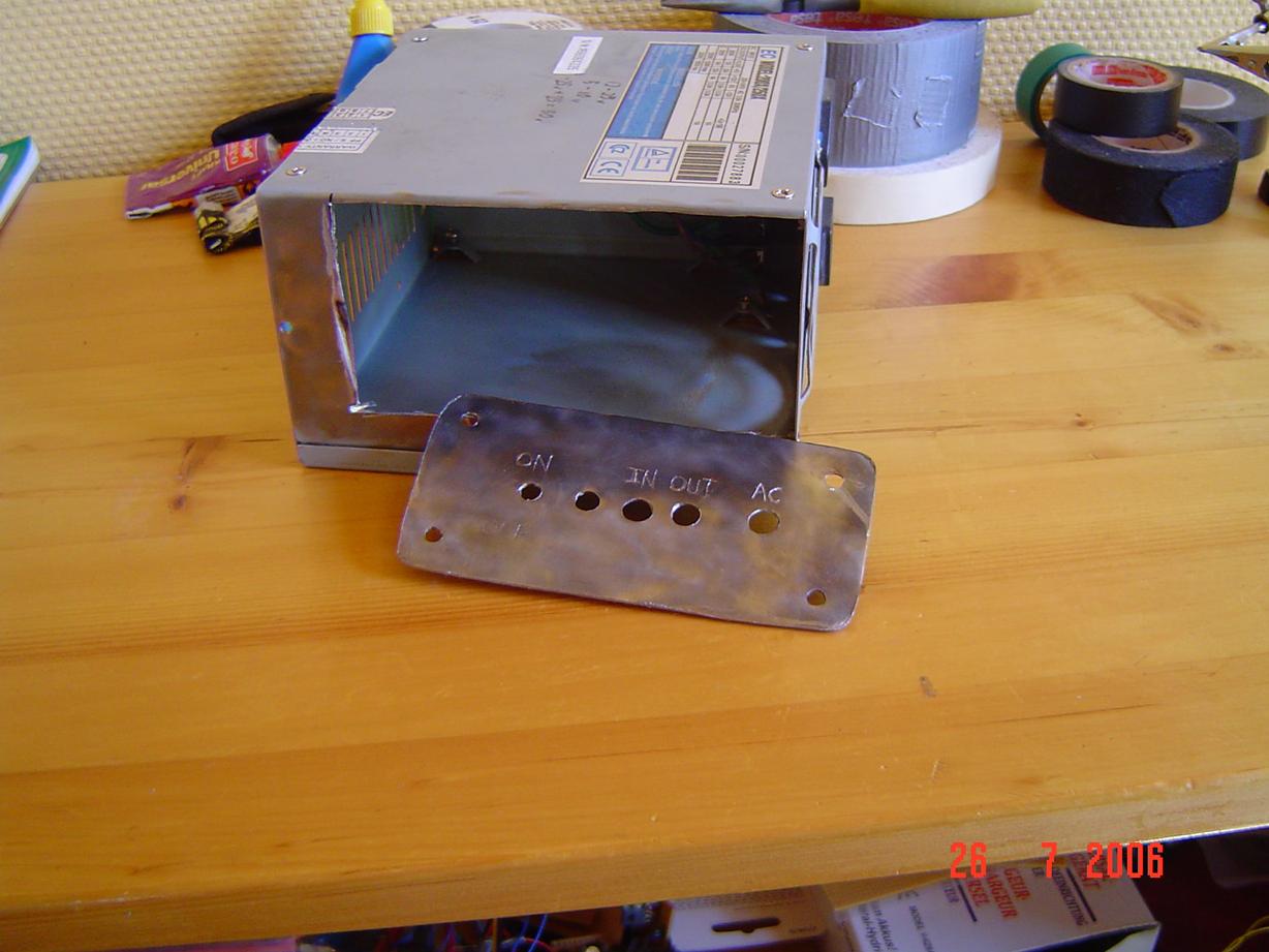
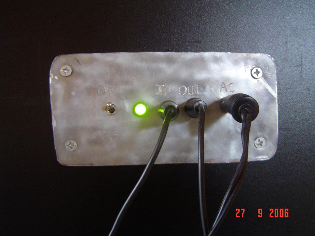
Next up is the control panel which is important for any DIY stereo system otherwise some fool might think you bought it from a store. I didn’t have metal or metal-working skills at the time, so I improvised. The picture is self-explanatory.
Next up wire everything together and hope it works. If so, its time to start wrapping things up. Decide which speaker should be the subwoofer, and open it up. The only way to enter many loudspeakers is through the large bass speaker, which can be unscrewed. Inside you will find fiber-glass insulation which is not good for your health. Discard it carefully, or save it so you can put it back in the speaker afterwards. It may or may not affect the sound, depending on how audiophile you are.
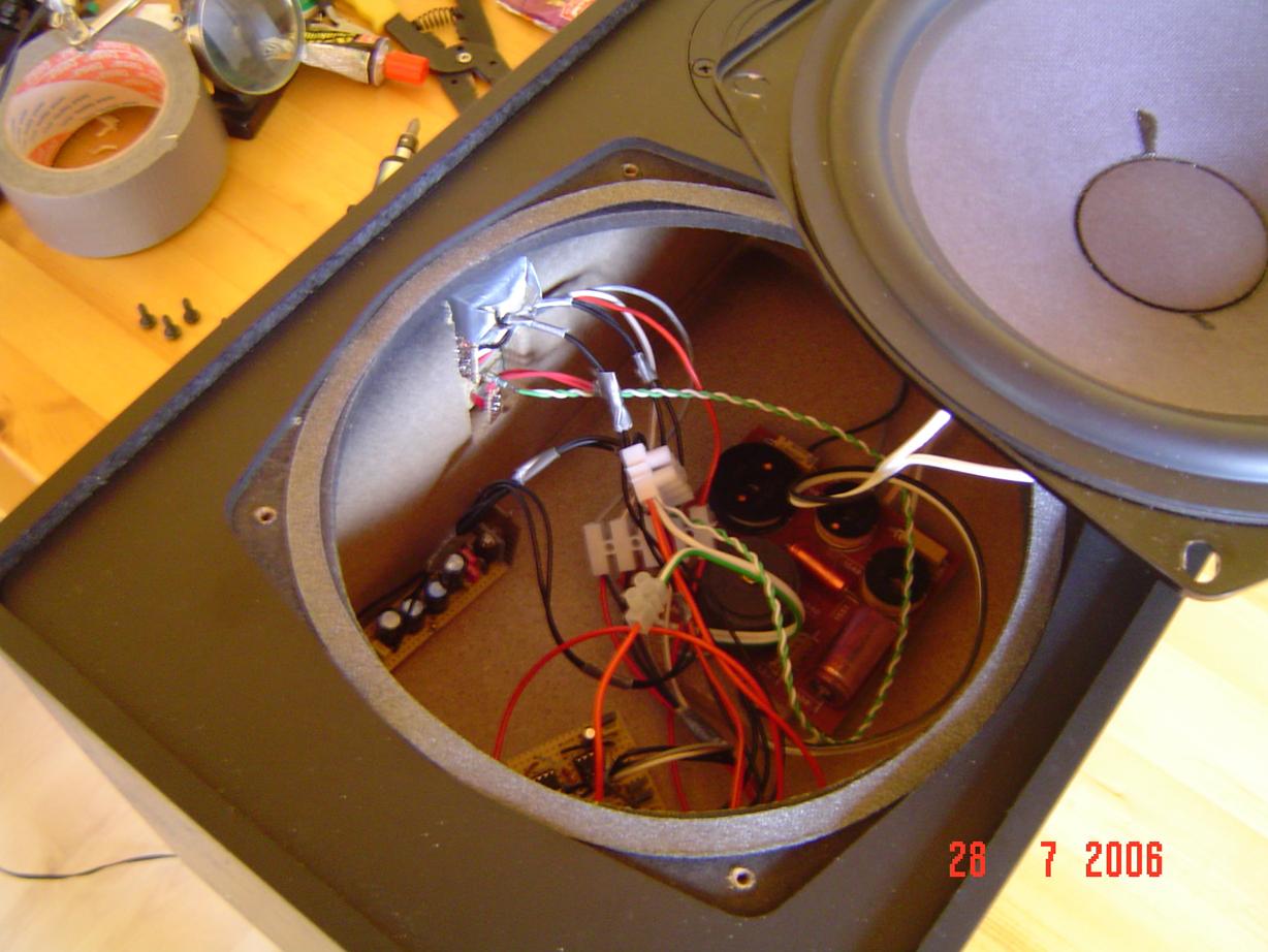
This is what you will end up with. You can see the built in cross-over filter inside, most speakers will have these. Cut the tweeters connections, as they will only play higher than bass frequency distortion from now on. Depending on your skill you will have something that looks better or worse than my setup.
Using professional connectors and hook-ups for the AC, IN, OUT, and a nice locking switch and LED is a must. The LED is not really as bright in RL as in the picture.
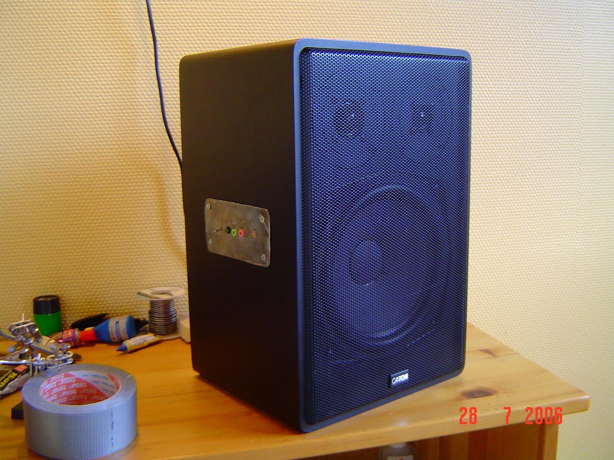
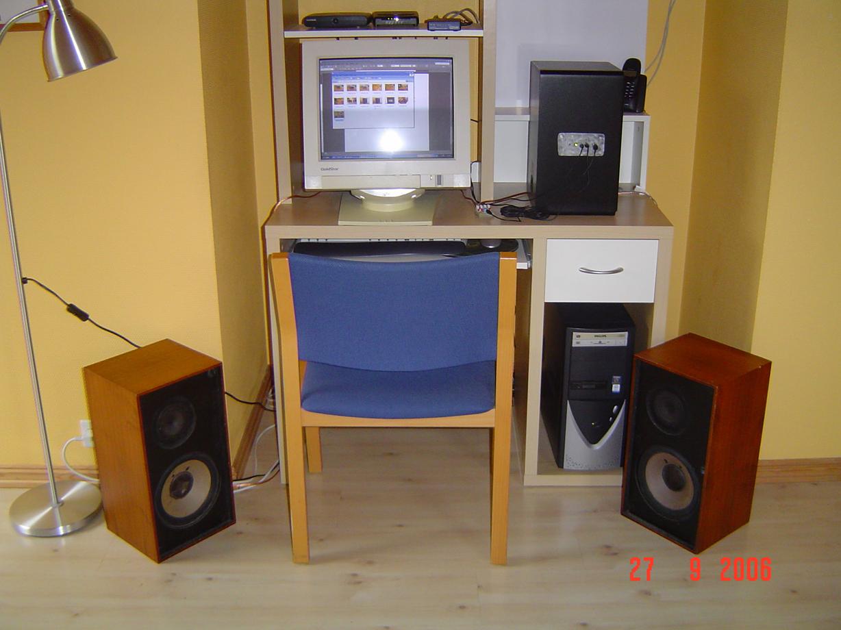
And there you go! This “guide” is far from complete, but is should give you a good push in the right direction. This system is not hi-fi, but good for a beginner in DIY audio.
![]()
![]()
![]()
![]()
Disclaimer: I do not take responsibility for any injury, death, hurt ego, or other forms of personal damage which may result from recreating these experiments. Projects are merely presented as a source of inspiration, and should only be conducted by responsible individuals, or under the supervision of responsible individuals. It is your own life, so proceed at your own risk! All projects are for noncommercial use only.
 This work is licensed under a
Creative Commons Attribution-Noncommercial-Share Alike 3.0 Unported License.
This work is licensed under a
Creative Commons Attribution-Noncommercial-Share Alike 3.0 Unported License.
4498 unique visitors since 28th June 2020.