
DIY PIC Programmer
Since buying a commercial PIC programmer will often cost more than any single PIC project altogether, the DIY solution well worth the effort. I built my entire programmer for no more than 15 dollars. The programmer is designed by David Tait and modified by Bob Blick. You can get the schematic and rest of the info from http://www.bobblick.com/techref/projects/picprog/picprog.html.
So that’s how great it can look! If you’re as lucky as me and find a parallel port female and cable, the programmer can be very sleek. One important thing to notice is the input voltage, it must be over 15 volts or the MCLR voltage will not be high enough. This programmer is very reliable and will work every time once configured correctly.
For burning .hex files I use ICprog. To get ICprog to work do the following;
Download ICprog and NT/2000/XP Driver.
Extract Icprog to any folder
Extract Driver to same folder
Run ICprog, ignore error messages. If hardware setup appears, go to step 7, then step 4.
Settings -> Options -> Misc -> Disable NT/2000/XP driver
Enable Disable NT/2000/XP driver, allow ICprog to restart
Allow driver to be installed
Now after opening the program, press F3, and set the following, if using a 7407.

You’re set!
Troubleshooting
If you get an error at 0000h, open ICprog -> Settings –> Hardware Check. With the programmer plugged in, without a PIC, check off each choice.
Enable MCLR should give 13-14 volts at pin 4
Enable VCC should give 5 volts at pin 14 and light the LED
Enable Clock and Data Out will change the output voltage at either pin 12 or 13.
Test Program
Here’s a little something to make sure that the programmer is working properly. Download blink.hex and burn it to a PIC16F84A, then build the following schematic. If everything works you should have an expensive blinking LED.
Update:
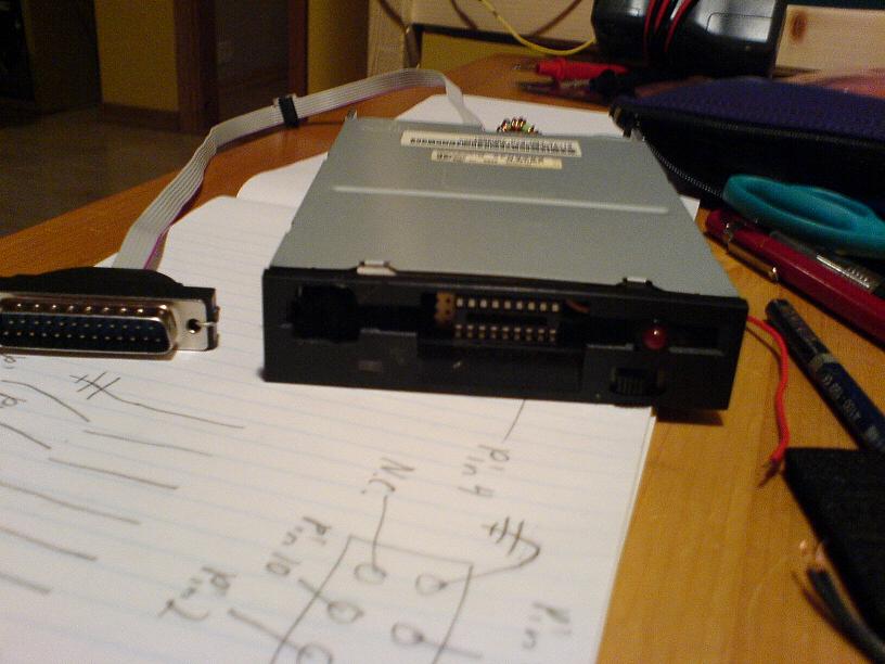
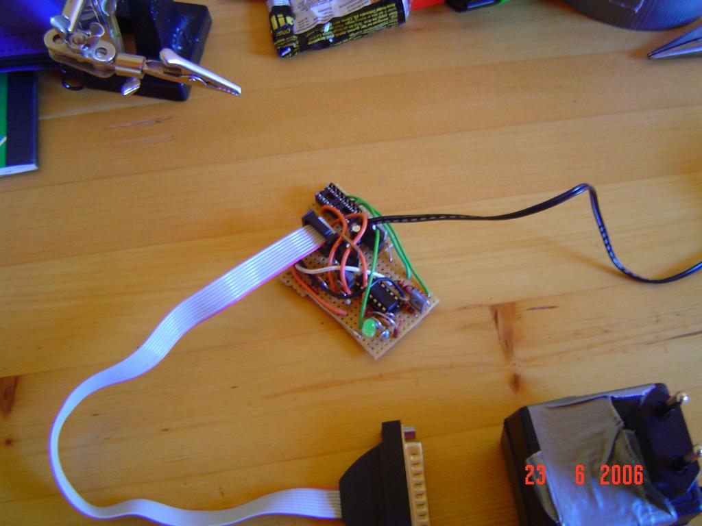
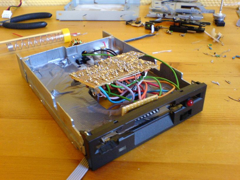
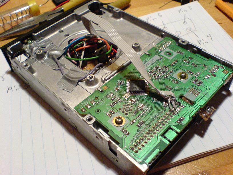
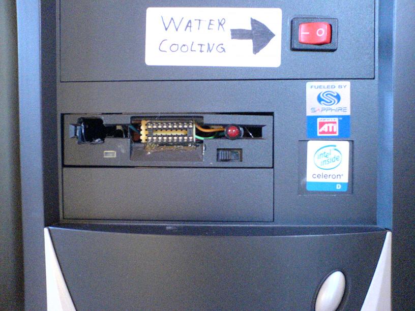
I built the PIC-programmer into a spare floppy disk, greatly improving usability. The pictures describe the construction process. The extra long parallel port cable was made from a standard IDE cable. The I/O for the programmer is soldered to the existing I/O port, after cutting the traces. A small joule thief like boost converter is used to supply 16V for the regulated 13V line.
This is the boost converter. Inductor is center tapped, and non-critical. The transistor heated on me, so you may want to experiment with different component values.
![]()
![]()
![]()
![]()
Disclaimer: I do not take responsibility for any injury, death, hurt ego, or other forms of personal damage which may result from recreating these experiments. Projects are merely presented as a source of inspiration, and should only be conducted by responsible individuals, or under the supervision of responsible individuals. It is your own life, so proceed at your own risk! All projects are for noncommercial use only.
 This work is licensed under a
Creative Commons Attribution-Noncommercial-Share Alike 3.0 Unported License.
This work is licensed under a
Creative Commons Attribution-Noncommercial-Share Alike 3.0 Unported License.
4532 unique visitors since 28th June 2020.