A small Tesla coil will have a high resonant frequency, making
conventional driving techniques difficult. What were once low
capacitances suddenly seem huge, and insignificant switching times
become a considerable portion of the switching period. A whole array
of new problems arise as frequency increases. However small coils only
need small amounts of
power to make a decent spark-show, allowing for simpler topologies.
Originally I had intended to run this coil off-line with a half-bridge
but I was unable to achieve decent gate drive through the GDT. So
instead I switched to class E, which only requires one switching device
and no GDT.
Notice: Although this circuit works,
for a class E coil you should use a fixed frequency oscillator. This is
because the output stage must be carefully tuned to your drive
frequency, and any small deviation either frequency or loading will
increase losses. See my other class E coil for a fixed frequency design.
Click on the schematic for a
larger image.
Circuit Function: The
phase locking is preformed by the 4046 chip. First some basics. The
4046 has an internal VCO, or voltage controlled oscillator. It's
frequency is controlled by the voltage at pin 9. The 4046 also has
internal phase comparators, in this circuit only phase comparator 1 is
used, which is just a XOR logic gate. First one sets the frequency
range of the internal VCO with the 100pF capacitor, and resistors on
pins 11 and 12. The pin 11 resistor sets the upper frequency, while pin
12 the lower frequency. By adjusting the voltage at pin 9 the VCO
frequency can be moved up or down between the set frequency points. Pin
4 is the VCO output, which will oscillate regardless of input. This
allows it to start the SSTC, which in turn provides feedback through
the secondary base current transformer. The base current signal and the
output from the VCO itself are compared by a XOR gate. (The VCO output
is actually sampled at the IRF630 drain, due to delays in the driver
transistors and IRF630 itself.) The output from the XOR gate is a PWMed
signal, which represents the phase difference between the VCO output
and base current itself. Since the VCO is controlled linearly by the
voltage at pin 9, pulsed DC would simply send it to max frequency and
back down again. What is needed is a steady DC voltage proportional to
the PWMed signal, which is created by the 120k resistor and 1nF cap.
The VCO can be biased by changing the constant voltage at pin 9 with
the potentiometer. This effectively allows one to adjust the phase
angle. Music can be modulated into the output signal by inserting it
into pin 9. Unfortunately the corona hisses and distorts the music.
Class E is almost as simple as it looks, basically
one switches in
resonance with the series resonant circuit formed by the primary
inductance and matching capacitor. The whole point is to tune the
primary and resonant capacitor until the circuit is critically damped
(doesn't ring below zero), and turn on the mosfet just
as the voltage reaches zero. This allows the mosfet to turn on
with no
voltage across it, ZVS, which eases switching and decreases switching
losses. Damping of the resonant circuit is done by adjusting the
primary coupling. Tighter coupling causes energy to be drawn from the
primary faster, which causes more damping. Unlike conventional SSTCs
coupling should be fairly loose, almost like a SGTC. Since this has
been elaborated much better before,
I'll point
you to some other pages which describe class E switching much better. Richie's
page and Steve
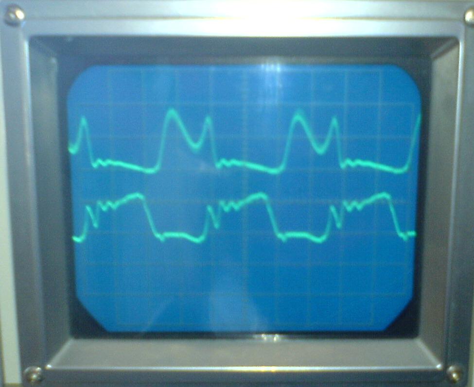
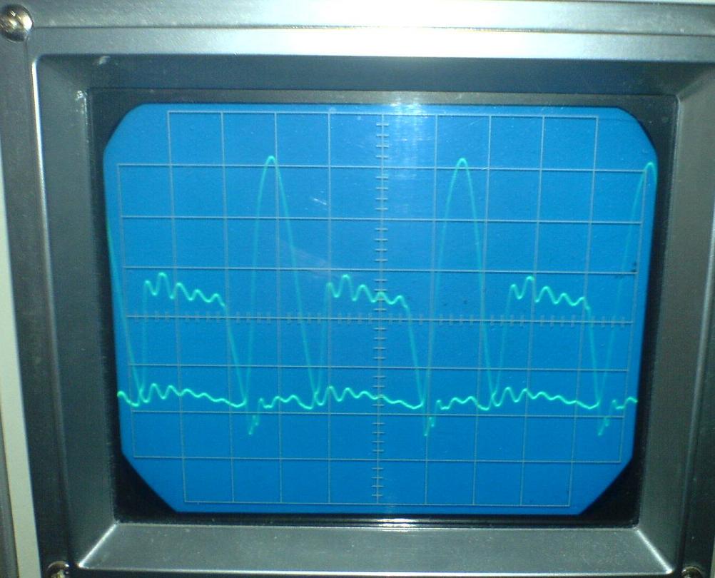
Ward's page are great resources. Steve Ward's page has simulated waveforms which
greatly help the tuning process. See if you can recognize these:
Bottom trace is gate voltage,
top is drain. The gate signal sure looks nasty when out of tune.
The phasing of the CT and
primary are
very important. While experimenting with an antenna I found that I
could only achieve breakout with the primary phased oppositely as the
secondary. The CT phasing was also critical for a phase lock, but I was
unable to determine which direction is required. The symptoms of
improper phasing are no breakout, breakout only after "coaxing" one out
with an arc or sudden loss of phase lock while tuning.
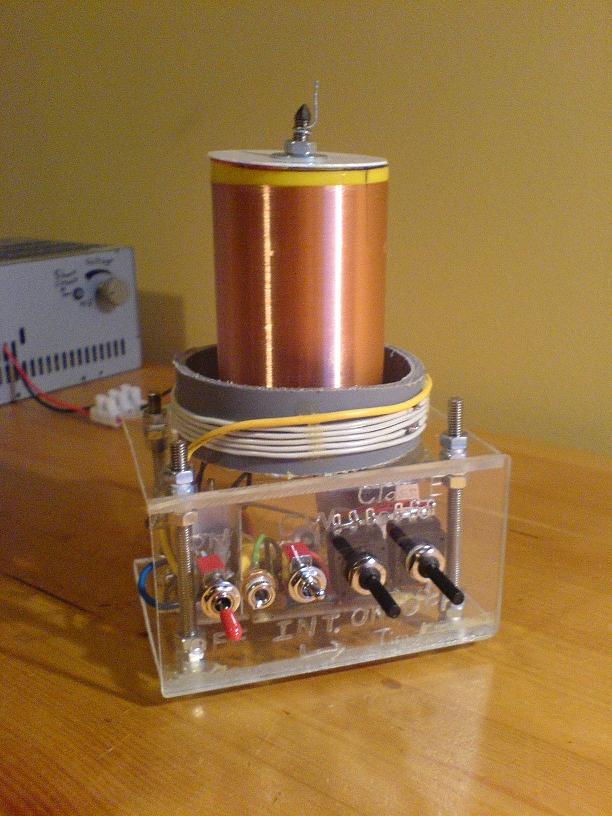
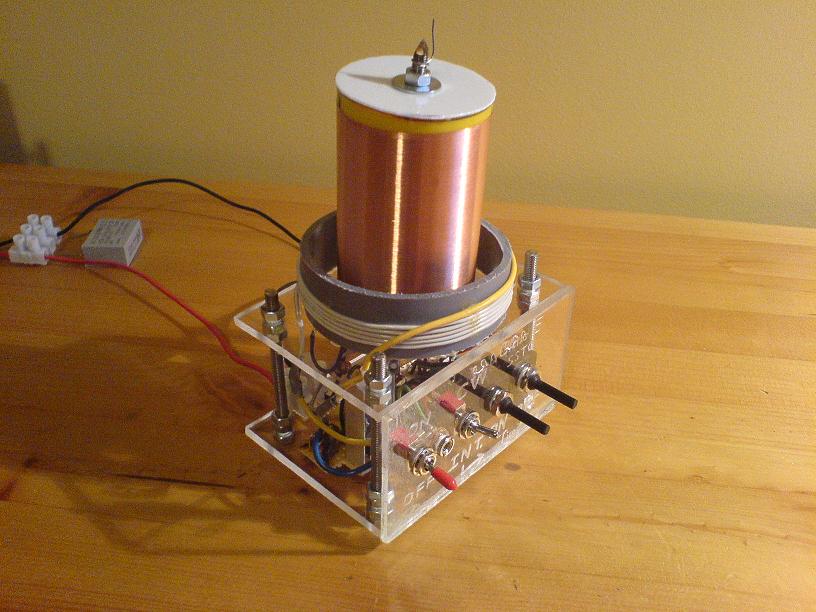
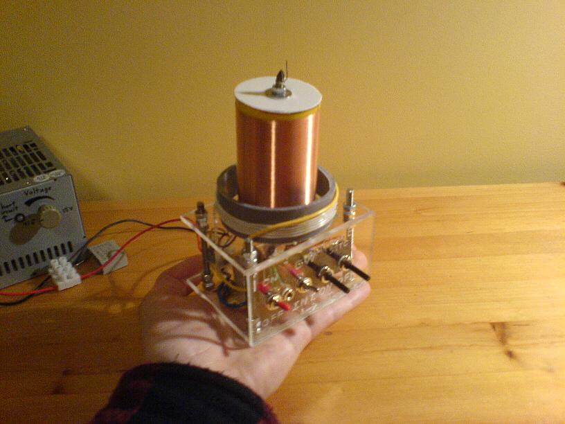
My coil draws about 80W from 50V, and runs at 1.38MHz. The secondary
former is 5 diameter * 8 cm tall. The entire coil with control
electronics fit in the palm of my hand, hence the nickname palm-top
SSTC.
Youtube Video!
Disclaimer:
I do not take responsibility for any injury, death, hurt ego, or other
forms of personal damage which may result from recreating these
experiments. Projects are merely presented as a source of inspiration,
and should only be conducted by responsible individuals, or under the
supervision of responsible individuals. It is your own life, so proceed
at your own risk! All projects are for noncommercial use only.

 This work is licensed under a
Creative Commons Attribution-Noncommercial-Share Alike 3.0 Unported License.
This work is licensed under a
Creative Commons Attribution-Noncommercial-Share Alike 3.0 Unported License.