Ever since seeing the first bluetooth controlled RC car I wanted to
make one. For those who haven't seen it, it used a serial port
Bluetooth module (about 200 USD), a "Mini SSC II" serial servo
controller board (roughly 50 USD) and an old RC car. Here's a mirror link
to the project.
Needless to say it was
unnecessarily expensive, which really put me off. So years passed until
I suddenly stumbled across some really cheap GP-GC021
bluetooth modules on ebay. (Update: Since then I've found an even
cheaper unit which is superior. See the RF-BT0417C,
and since then, even cheaper units have appeared. The most commonly used is the HC-05, or HC-06)
What made them so
special was that they were directly TTL compatible UART modules. Not
only would I save vast
amounts of money, but
also effort by not having to use RS-232 voltage levels. I decided to
use the RC car
from my previous RF control endeavors, but also add servo steering so
it
would be
more fun and practical to use. Given my previous work on the COM laser
turret, controlling motors over
a serial protocol was no difficulty, and the firm- and software
required was already written. The only new thing required would be
implementing servo control over a serial protocol.
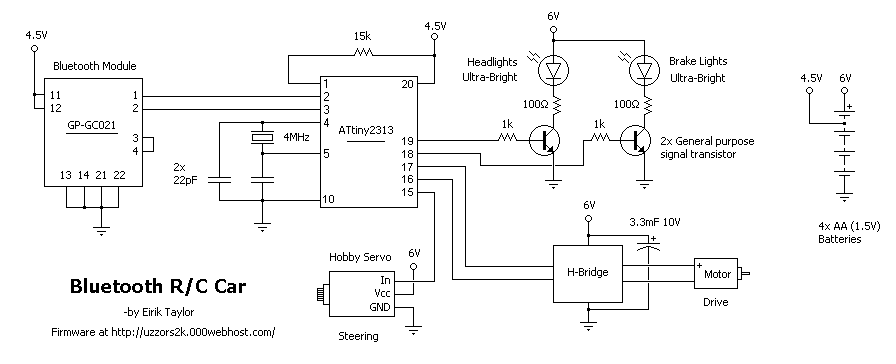
I've simply connected the UART of the bluetooth module to the built-in
UART module in ATTiny2313 so they can communicate directly with
one-another. A portion of PORTB is used to control the various
functions in the model car. The ATtiny2313 firmware goes through a loop
which consists of reading the UART, and then setting the outputs and
servo position. First all the outputs are set, except the servo signal.
A simple bit pattern where each of the six most significant bits
represent a value. A one is true, 0 false, where descending from MSB we
have : | Headlights | Brakelights | Forward | Reverse | Left | Right |
Unused | Unused |. Based on the value of the Left or Right bits the
position variable is set to a preset value representing far left or far
right. I used preset values due to my DIY servo steering not using the
exact center of the servo rotor, and some unevenness in the mechanics.
After the position of the servo is set, the remaining bits are simply
sent to PORTB, lighting lights or starting the engine. After this a
function is called which positions the servo. Due to the way I wrote
the program, ie not using interrupts, the car can only respond every
15ms. The firmware was
written in MikroC Pro from Mikro Elektronica. I've been toying with the
idea of making some better firmware using AVR-GCC, which is my compiler
of choice now. After programming for my MIDI and ROV project, my grasp
AVR programming is much better. Adding sensors, PWM control for the
motor, and better servo control are some of the things I'd do.
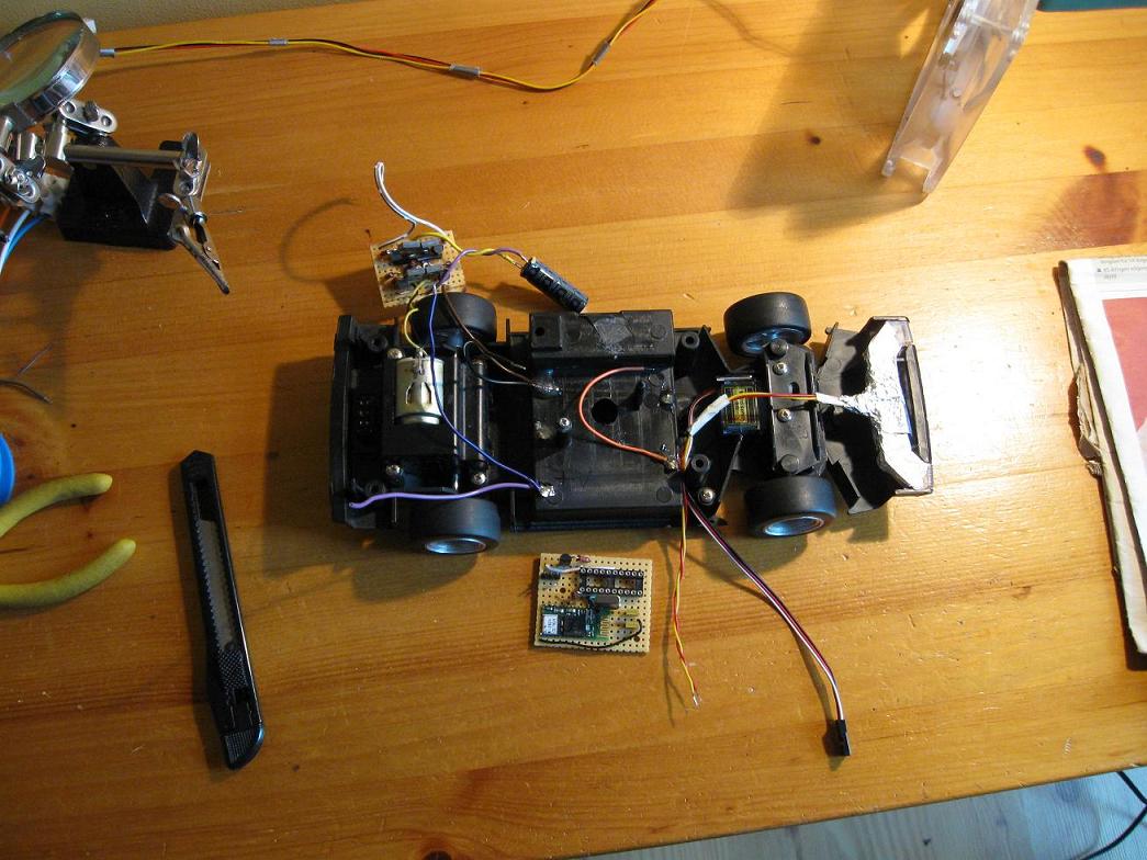
I've received a bunch of emails asking how I soldered the bluetooth
module to the circuit board. Basically you have two options here
because of the weird footprint it has: You can either design a special
breakout PCB for it, which I'll do if I use one of these modules again.
OR you can do what I did, which is solder it to the topside of some
veroboard, by using old component leads. There are only ten connections
to be made, so it's not a big deal.
In addition to firmware for the ATtiny2313 some software is needed for
the controlling bluetooth device. I wrote a small program in
Visual basic, which
can control the car through any serial port, real or virtual. This
allows the use of USB bluetooth modules which have a serial port
profile. I've
added the ability for
users to control the car using the keyboard: W for up, S for down, A for left and D for right. I've
also written some apps for various phone models, which are described below.
The Java App
Controlling the car over bluetooth on a PC is great, but cell phones
also have bluetooth. During the COM Laser Turret project I
dabbled in java and fooled around trying to send serial commands over
bluetooth to the PC. Eventually I found this tutorial
on interfacing with GPS modules over bluetooth. So I took the source
code, and stripped it down until I understood the basics, and had an
application that would search for, and connect to bluetooth devices.
Implementing a control menu for the car and sending serial commands was
rather easy after that. The bluetooth program works perfectly on my
k750i, not at all on my father's k810i and will only receive commands
on my mother's N73. So your mileage will
vary unfortunately. Some firmware types may not even allow bluetooth access from java apps. The java app
itself was written in Netbeans, which is free and open source. I have included the source
files and hopefully commented sufficiently for the code to be understandable.
Download the complete package, including schematic, firmware, software,
cell phone app and source code. Android source files are also included.
Update 6.11.10
Satyamfifa
found a fix for the Java app, making it work on his phone: "the j2me
code was not working on my Nokia 2700 classic. i added flush() after
write() and it started to work". I no longer have Netbeans, so if you
want to use this app on your phone, try the fix mentioned here and
recompile the app yourself. Hopefully it will solve the problem.
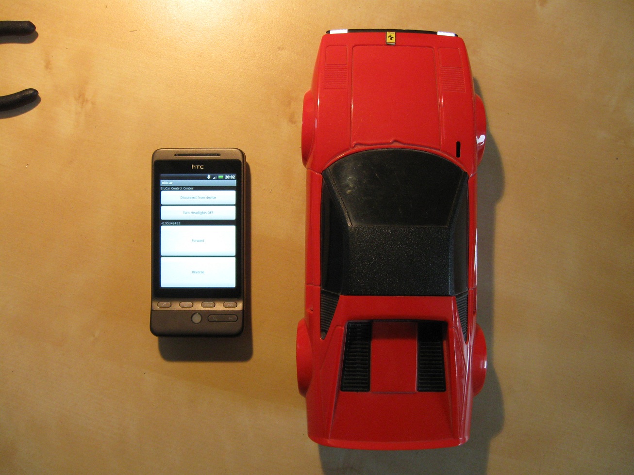
The Android App
08.06.10
Since the last update I've purchased an HTC Hero, which is awesome.
Their Dev
Guide
proved real useful, and makes learning how to program for Android a
breeze. Anyway, to really prove the worth of my Android phone, it had
to be able to control this car. The first program I made was a little
soundboard app, this taught me the basics, and from here the only real
hurdle was the bluetooth communication itself. In the end I had to use
one of the bluetooth examples (Bluetooth Chat), because why change
perfection? The app uses the phone's internal accelerometers for
steering, and two large buttons for forward and reverse. Much easier to
use than the k750i.
As for the app itself, finding bluetooth devices is done using a slightly modified version of the
"DeviceListActivity.java" from the bluetooth chat example. This simply
finds paired devices, and ones in the vicinity, and displays them in a
menu. The on-screen buttons simply control the data byte sent to the
car. Again, I hope I've commented enough for it to be useful. All the needed source files are available in the zipped download above.
The ready to install program is on the Android Market, simply search
for "BluCar" and it should pop up. Alternatively, it's also in the
complete project package above. Know that use
of bluetooth requires Android 2.01 or better.
Youtube Video
Adding Servo Steering
The construction of a new servo steering system was a major part of
this project, but not directly related to microcontrollers or
bluetooth. Since it might be of use to someone who decides
to build this project, I'll include some info on what
I did. The original
steering system of the car was made so the car would drive straight
forward, and when in reverse turn to the left. This way only a two
channel remote is needed to provide steering, which saves complexity of
the electronics. And that was important considering that the original
circuit contained only discrete components! This was lucky for me in
the sense that it would only
require some simple modification to provide full directional steering.
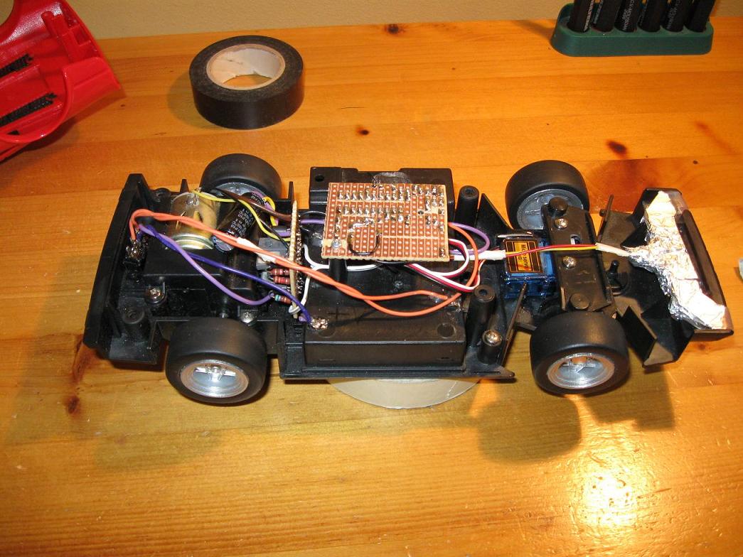
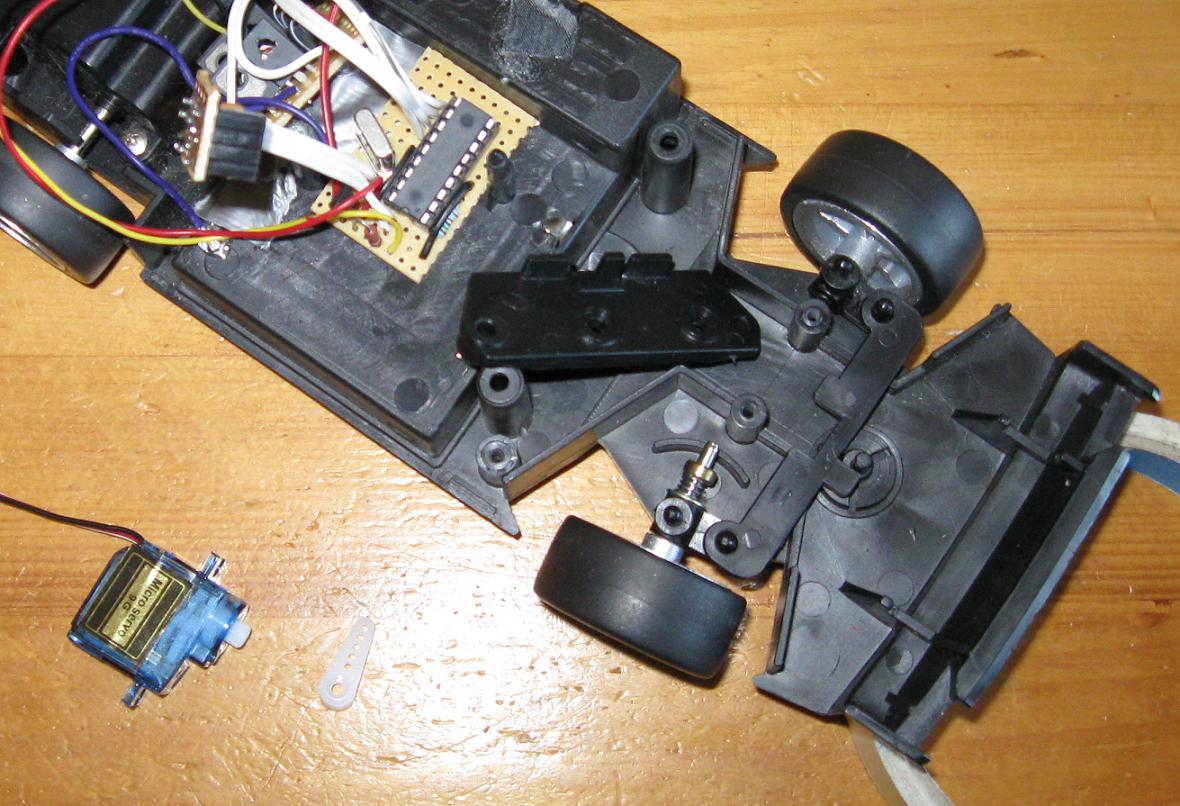
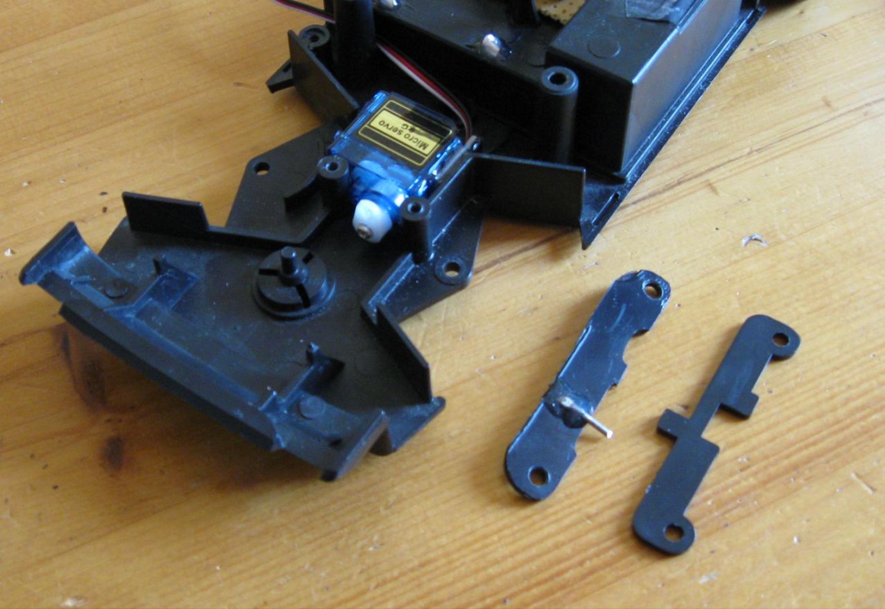
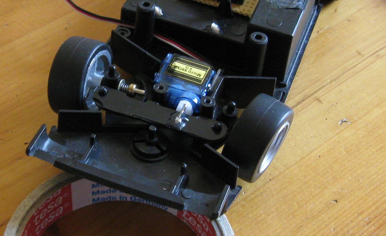
First is an image of the original steering system and the servo I
planned on using (see left). I found an ebay auction for four small 9G
hobby
servos, which seem quite adequate for a small indoor RC car. Since I
didn't want to damage the car too badly in case I failed to make the
servo steering work, I fabricated a new steering bracket using ABS
plastic, taken from a CD-ROM drive. The plastic was almost as
thick as the original stuff, and seems identical otherwise. I cut out
the piece using the original as a template to ensure the wheels would
stay aligned with one-another. The piece was shaped, and a thick pin
(leg from a 5A diode) was epoxied to it to serve as a guide. The servo
itself was epoxied in the space behind the wheels, where it fit nicely
after some work with my Dremel. I'm afraid the one I put in might fail
some day, and with all the epoxy
I used to fasten it I might not get it out. Remember to allow for servo
replacement, as they do wear out eventually. The "arm" type servo horn
was fastened to the servo after being shortened, and the holes cut into
a long track. As is evident in the picture below, as the servo rotates,
the pin will be forced to move horizontally either left or right.
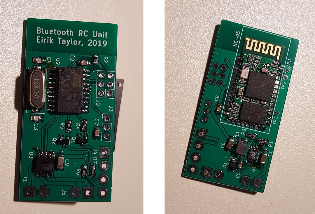
New control firmware
29.09.19
I dug this old creation out of the closet recently, and didn't use it for long before I had a new project on my hands!
The old control protocol did not allow for fine control of motor power, or servo setting, and in addition the car would
continue with the last received command any time the connection was lost. This is generally not a good idea for RC devices,
where a defined "loss of connect" command is desired. In the case of the RC car I really want it to stop as soon as the
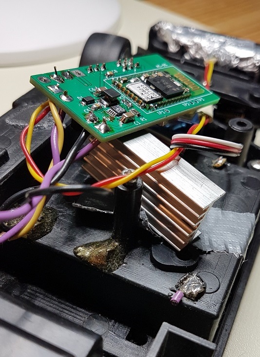
connection is lost. The hardware side of things wasnt much better, as it was difficult to reprogram the board, the old
motor was slightly damaged during my previous soldering attempt, and had now started to fail intermittently, and the bluetooth
connection was often lost. On reviewing the protoboard layout, I saw I had used no decoupling capacitors, no local capacitance,
and place the antenna of the bluetooth module directly over some copper traces! All in all, I had found enough issues to
warrant a redesign!
I started with the hardware redesign, which there is not much to say about. Simply using best practices, and correcting the issues
mentioned above. In contrast to last time, I added an onboard DC-DC converter so the exact battery voltage is no longer critical,
and so all devices receive the correct voltage. This allows me to use a modern LiPo battery, which is rechargable and has much
higher current capacity. I also decided to use an integrated full-bridge driver to control the motor, instead of the discrete,
DIY transistor based version I had used previously. The motor was also replaced with a standard toy motor. I'm not completely satisifed
with the new design however, as testing has found a few issues. For one thing the motor drive chip becomes very hot. The next
hardware iteration should use a more efficient chip. Also, better attention must be paid to the PCB layout. Currently all heat producing
components are in the same area on both sides of the board. There is also little room to place heatsinks. Just to get the fullbridge
to run for more than a few seconds, a large heatsink was required. The other issue is that the servo is run directly from a 2-cell lipo.
This works, but it heats up. A dedicated 5V supply should probably be provided for it. Other than that, the new hardware delivered
everything it was supposed to!
The software was updated with a new control protocol, which supports variable power for the motor, and exact setting of the servo.
In the firmware for the car, I also added a watchdog timer, so the car returns to an idle state if no new message is received within
a given timeframe. The Android app has received an update, and can be run with both the new and old protocol. The new protocol is
simply a command byte, followed by a value byte. The commands are:
Disclaimer:
I do not take responsibility for any injury, death, hurt ego, or other
forms of personal damage which may result from recreating these
experiments. Projects are merely presented as a source of inspiration,
and should only be conducted by responsible individuals, or under the
supervision of responsible individuals. It is your own life, so proceed
at your own risk! All projects are for noncommercial use only.

 This work is licensed under a
Creative Commons Attribution-Noncommercial-Share Alike 3.0 Unported License.
This work is licensed under a
Creative Commons Attribution-Noncommercial-Share Alike 3.0 Unported License.