This is a
great way to get a cheap lab
power supply, and serves as an introductory project in electronics. It
was
actually my very first successful electronics project. Computer
PSU's supply a good range of low voltages, which is useful for all
sorts of smaller
electronics projects. Your garden variety ATX supply has a +5, +12,
+3.3, -5 and -12 volt rails. The positive 5 and 12V rails can supply
enough amps to power projects consuming hundreds of watts, while the
other rails are rated for just one amp of so. The negative rails have
actually been regulated by 7905 and 7912 ICs in many of the supplies
I've disassembled.
However these PSUs won't function outside of a computer without some hacking first. Most of what's written here
applies for AT supplies too.
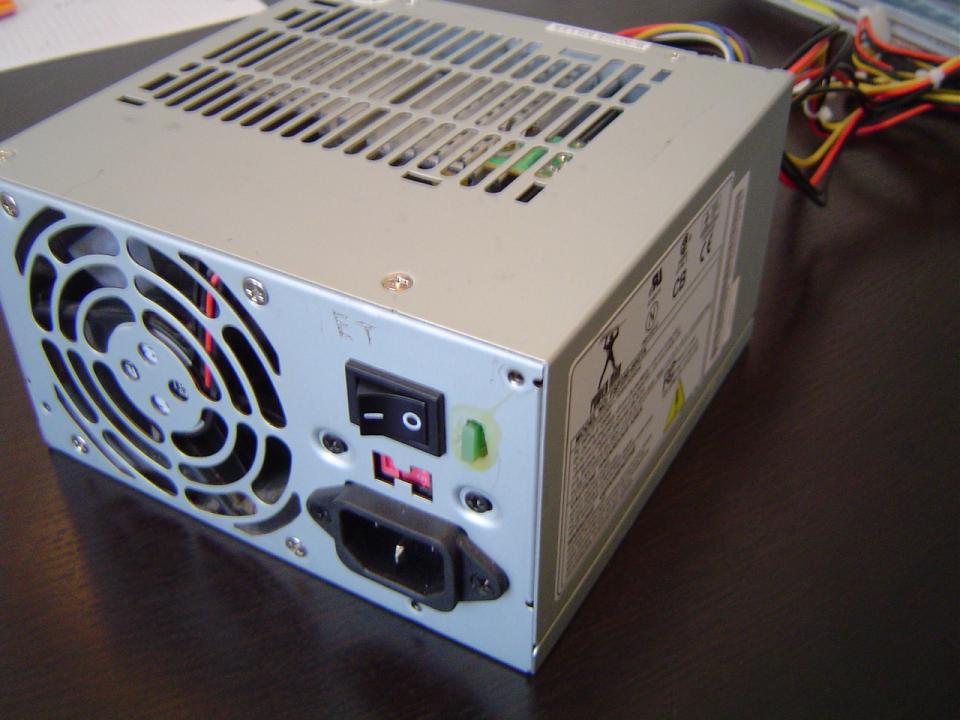
Finished supply, with indicator LED.
First you
have to know which voltage is
on which line. Typical wiring configurations for AT and ATX PSU's are
shown below.
AT Power Supply Pin out
Pin
Name
Color
Description
1
PG
Orange
Power Good, +5 VDC
when all voltages has stabilized.
2
+5V
Red
+5 VDC (or n/c)
3
+12V
Yellow
+12 VDC
4
-12V
Blue
-12 VDC
5
GND
Black
Ground
6
GND
Black
Ground
ATX Power Supply Pin out
Pin
Name
Color
Description
1
3.3V
Orange
+3.3 VDC
2
3.3V
Orange
+3.3 VDC
3
COM
Black
Ground
4
5V
Red
+5 VDC
5
COM
Black
Ground
6
5V
Red
+5 VDC
7
COM
Black
Ground
8
PWR_OK
Gray
Power Ok (+5V
& +3.3V is ok)
9
5VSB
Purple
+5 VDC Standby
Voltage (max 10mA)
10
12V
Yellow
+12 VDC
11
3.3V
Orange
+3.3 VDC
12
-12V
Blue
-12 VDC
13
COM
Black
Ground
14
/PS_ON
Green
Power Supply On
(active low)
15
COM
Black
Ground
16
COM
Black
Ground
17
COM
Black
Ground
18
-5V
White
-5 VDC
19
5V
Red
+5 VDC
20
5V
Red
+5 VDC
In the best of cases
shorting the green "Power Supply On" wire
to ground will be enough to turn on the PSU. To run
outside of a computer most ATX
PSU's require a minimum load. A power resistor between +5v and ground
or +12V and ground is used. One 2.7Ω 10W for the 5V line or 10Ω 15W for
the 12V line will work with most PSU's. In some cases Power OK must be
shorted to ground to make the PSU run. Putting a LED on Power Ok will solve this and indicate when the
PSU is on. A reader has informed me that the new 24-pin ATX supplies
have a sense wire which must be connected to the +3.3V rail. This sense
wire is usually brown. These are usually the only steps it takes to
start a PSU.
If all is good you
should be getting 12V on the yellow wires and 5V
on the red wires, give or take 0,5V. If the voltages are a little low
the minimum loads might need to increased, which is to say the load
needs lower resistance.
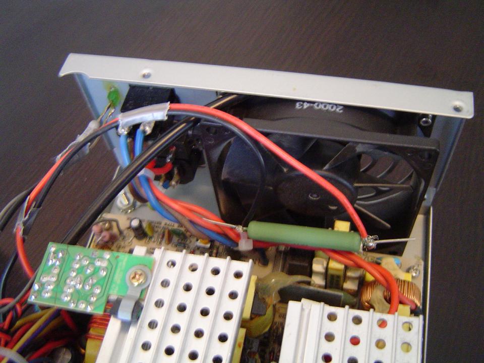
Minimum load installed close to fan.
Variable Voltage?
Converting an
ATX supply for variable voltage is surprisingly simple, and only
takes one potentiometer. The PSU's I've hacked used a KA7500B for PWM,
but the TL494, HA17339, KIA494, KA7500, IR3M02, and MB3759 are drop
in equivalents of the KA7500B, so if your PSU uses one of these you
are in luck.
To regulate the voltage down:
Find the
resistor which goes from pin 14 on the PWM IC to pin 2. Now simply
place a 10K potentiometer in series with this resistor and pin 14.
What this does is mess with the regulating reference. Pin 14 is the
internal regulated +5V from the IC. The resistor we put a
potentiometer in series with is part of a voltage divider, which
supplies ~2.5V originally. Turning the pot decreases this
voltage and the PWM IC thinks the output voltage is increasing, so it
compensates by reducing the duty cycle. Reduced duty cycle means less
power and less voltage. Regulating the voltage down can be done
without modifying other components.
To regulate the voltage up:
If you want the
PSU to live for long you'll need to replace the
rectifiers and
capacitors. The absolute maximum voltage I've experienced was 25V, so
30V
capacitors and rectifiers will do. Of course this voltage may have been
limited by the capacitors/rectifiers shorting on me!
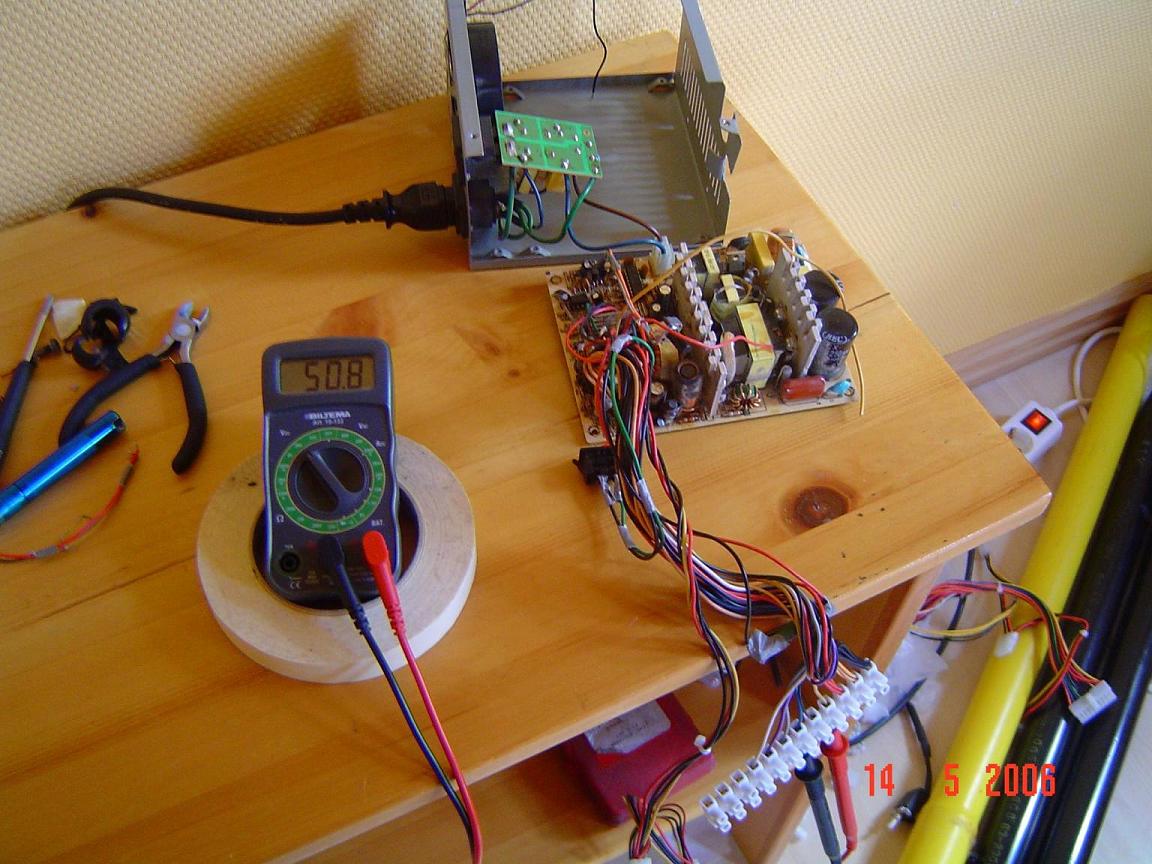
50.8 volts from the +12V and -12V rails combined.
First find pin 1
on the PWM IC. Then trace back along the circuit trace until you find 2
or 3
resistors. These resistors should be connected to one or both of the
power lines (+12V and +5V) and ground. If shorting these resistors
trips the short-circuit
protection you have most likely found the right ones. What the
resistors do is act as a voltage divider, developing ~2.5V typically at
pin 1. The reference voltage can be checked on pin 2 while the PSU is
running. Unsolder one end of both resistors at the pin 1 end, and
solder the ends together outside
of the circuit. Now solder a potentiometer in series with the resistor
pair and
pin 1, completing the circuit once again. The potentiometer should be
about twice as large as the resistors. 10-20K for the potentiometer
will often work fine. Turn the pot to 0 ohms before you turn on the
PSU, that way the mod hasn't been "enabled" yet and everything
should work as normal. This
modification works much like the previous one. The resistors we put a
potentiometer in series with form a voltage divider, which feeds 2.5V
to pin 1. Their voltage source is the output voltage, which under
load will sink. A lower voltage on pin 1 means longer duty cycle and
more power. Turning the potentiometer reduces the voltage at pin 1
and the PSU thinks the output voltage has dropped, and thereby
increases the duty cycle to compensate.
Once the
potentiometer is installed turn on the PSU, and slowly turn the
potentiometer while measuring voltage. The PSU should
short. But before it can do that the voltage should have increased. If
you measured a higher voltage on the +12V or +5V rail before the
short you have the right resistors, if not solder them back in place
and keep looking. In my experience the PSU will short at 13-14V. The
next paragraph has info on how to disable the overvoltage shutdown.
If you need a
circuit diagram to follow things better, this one is similar to
almost every PSU I've come across. The feedback resistors are R25
and R26 in the following schematic, the ground resistor is R20 and 21
in parallel.
pavouk.comp.cz/hw/en_atxps.html
Disabling overvoltage shutdown:
Now you might
have noticed the PSU shorted at a mere 14v or so. This is because the
overvoltage protection kicks in. Overvoltage protection
works by setting pin 4 high, which sets maximum deadtime. A
transistor is often used to change the signal level, and disabling it
will prevent the overvoltage/short-circuit protection from kicking
in. Find pin 4 on the PWM IC, and trace back from it to the first
transistor you find. To see if it's the right one short the
collector and emitter together. If this shorts the PSU it's the right
transistor. Unsolder the transistor and remove it from the circuit.
Alternatively you could just wire a direct connection from pin 4 to
ground ensuring that it remains low.
Congratulations,
now your PSU hack is finished! Drill some holes and put the
potentiometers in place.
Disclaimer:
I do not take responsibility for any injury, death, hurt ego, or other
forms of personal damage which may result from recreating these
experiments. Projects are merely presented as a source of inspiration,
and should only be conducted by responsible individuals, or under the
supervision of responsible individuals. It is your own life, so proceed
at your own risk! All projects are for noncommercial use only.

 This work is licensed under a
Creative Commons Attribution-Noncommercial-Share Alike 3.0 Unported License.
This work is licensed under a
Creative Commons Attribution-Noncommercial-Share Alike 3.0 Unported License.