450V Capacitor Charger - Boost Converter
The boost converter is a DC-DC
converter, which basically stores energy in an inductor and then
releases it. What happens is voltage is
applied to the inductor, and current starts to flow through it. When
the mosfet switches off the current flowing through the inductor can't
stop immediately. In most cases this would result in the voltage at the
mosfet drain rising until current can flow again (avalanching of the mosfet or
just a dead mosfet), however the diode provides a path for the inductor current into the
capacitor bank instead. So for each period energy is stored in the
inductor and then sent onward to the capacitor. The 555 is used to
continuously pulse the inductor. The reason storing energy in an inductor before
sending it to a capacitor can be used to boost voltage is rather
simple. As stated earlier the inductor current is unstoppable and is
routed into the capacitor. This current represents energy stored in the
inductor which is slowly flowing out of it again (actually the current
ramping up during the on-time builds up a magnetic field,
the field then decreases during off-time. The inductor's energy is stored in this
changing field.) Since energy is stored in a capacitor as voltage
difference between the plates and results from current "flowing" in the
capacitor, the voltage must increase because the capacitor is accepting
current from the inductor. To keep accepting more energy from the
inductor the capacitor voltage must rise. NEVER run the boost
converter without a capacitor as the inductor energy has to go somewhere, and
avalanching through the IRFP450 is the only option left. The power
dissipated in the mosfet will (unless properly heatsunk) quickly kill
it.
The converter consumes around 3A,
and is designed for 12V use. The charge time for a 4700µF, 430V
bank is 30 seconds, meaning 15W of output power. W00t, 40% efficiency.
Greater efficiencies have been reported however. When the desired
voltage is reached the 555 is turned off
automatically, and the LED lights. The actual boost converter section
of the circuit consists of the 555 + timing components, IRFP450,
inductor and 500V diode. The rest is just there to stop the circuit at
the target voltage. The voltage sensing is based on a LM311 voltage
comparator, which as the name indicates compares the voltages at it's
inputs. If the positive input is greatest the output of the comparator
is positive. If the negative input is greatest the output is negative,
in this case 0V or ground. A voltage divider (the two 15k
resistors) is used to provide half of the supply voltage to the
positive input. A 1M resistor combined with a 10k resistor and 10k
potentiometer form a variable voltage divider. Look up calculators on
the Internet to see how this works. The 1nF cap is there to stabilize
the voltage. So with a voltage divider on the positive input providing
6V, and a variable voltage divider on the negative input, the
comparator output will start high, and go low when the target voltage
is reached. The comparator output is fed to the 555 reset pin, which is
active low, meaning it will reset or inhibit the 555 when the target
voltage is reached.
Note: All resistors are 1/4W. The inductor should have a current handling
capacity of at least 2A, and are often called chokes. Any value of 100
to 200µH will work. Other values close to this will also work to
some degree.
NEW! Make your own PCB!
I've made a PCB layout for using ExpressPCB so soldering the circuit together is easier if you can make
PCBs. Some assumptions were made as to the diode package and inductor
size, so check whether your components will fit first. Included in the
zipped folder is a .pdf file, parts list, and drawing of component
layout so ExpressPCB isn't required.
Download PCB files.
Reader Paul McInnis
bravely tried the first revision of the PCB design, which gave me some insight on what needed to be changed.
Inductance and Frequency
If you feel a need to modify the
circuit, I’ve made a frequency/ inductance/ power calculator. I'm
no engineer, but assuming all of the inductor energy is transfered to the
capacitor bank it should be correct. Download the spreadsheet
here.
You need to find a point where the inductor won't saturate, current can be
limited by on-time or inductance. You will probably want to get the
most power as possible too. Power is stored in the inductor and is
released during off-time. Since an inductor's stored energy is
0.5*L*I^2 and energy is released with each off-time a high frequency
combined with high inductor current will give the most power. (use a
small inductance for high frequencies) I'm unsure of the tradeoff's
here, but I guess the inductor's core material will be the frequency
limiting factor.
Troubleshooting / FAQ
If you have any questions, for the love of God check here before emailing me.
Also, try to understand the circuit function as this makes troubleshooting vastly more simple.
No, 9V batteries aren't good enough. If you're having problems upgrade to a bank of AAs, a motorcycle battery, an ATX supply or whatever.
If you hear a high pitched squeal everything should be working (assuming the switching frequency is still in the audible range), check
the connection to the capacitor bank if it's not charging.
If the timer is working but nothing is happening make sure the inductor, diode and mosfet are all connected
correctly. Also make sure you are using an inductor of sufficient inductance.
Capacitor charges to 12 volts? This means the MOSFET isn’t switching. Check the 555, IRFP450 gate, and drain with an oscilloscope.
Will only charge to XXX volts, then slows down or stops? This is almost always caused by too little
power. I’ve tested this design to 445V, so it will work up to there from 12V. See point 1.
Where to get components? Your local components supplier, google "components" in your language, possibly
"resistor" and find the first online store. If the store is any good they'll have what you need.
If you're green in electronics then try a 555 blinker circuit and comparator/op-amp test circuit first.
That way you have the 555 and 311 part down, and the rest is easy.
If your question is not on this list email me so I can put it here. ;-)
Test point voltages:
The voltage at pin 4 on the 555 and pin 7 of the 311 should be close to
12V when the circuit starts up. When the target voltage is reached this
voltage should drop to 0.6V or less.
The voltage at the positive input of the LM311 should be 6V, or half of
the supply voltage (V/2).
The voltage at the negative input should approach 6V or V/2 as the
capacitors approach the target voltage.
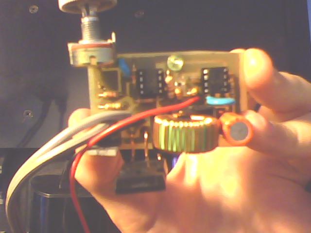
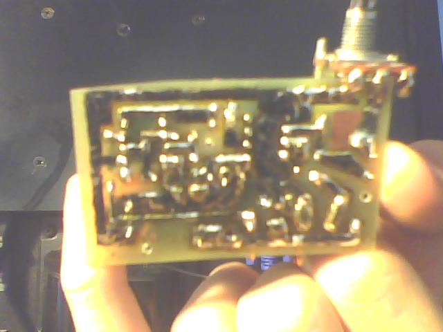
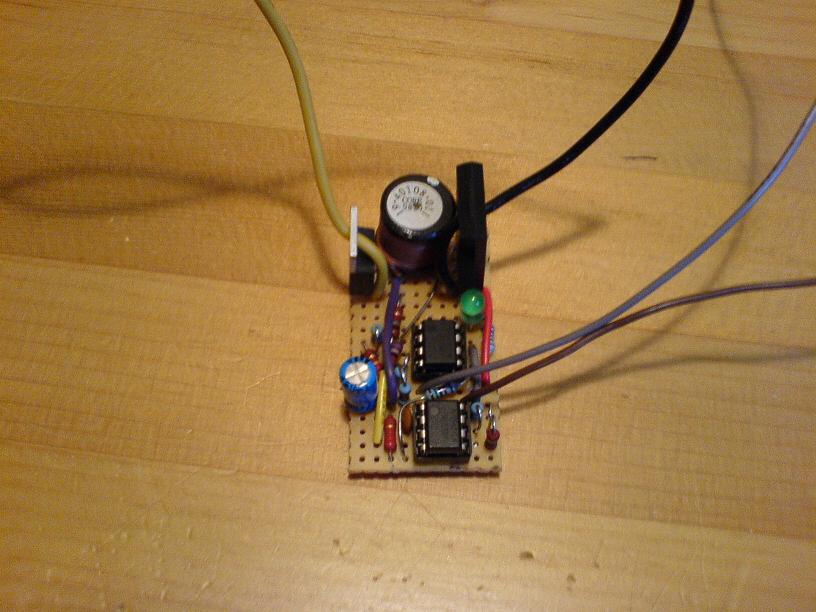
Pictures
As you can see they can be built quite small, using surface mount components can decrease size further. Use
a heatsink on the IRFP450 as it begins heating when the capacitor voltage rises above 400V.
This circuit has been built with success by numerous others, among them Electroguns.com.
Reader Edward Bennett sent in a shopping list suggestion for three major component dealers. For the heatsinks, I suggest scavenging them, or finding an old processor cooler.
Disclaimer:
I do not take responsibility for any injury, death, hurt ego, or other
forms of personal damage which may result from recreating these
experiments. Projects are merely presented as a source of inspiration,
and should only be conducted by responsible individuals, or under the
supervision of responsible individuals. It is your own life, so proceed
at your own risk! All projects are for noncommercial use only.

 This work is licensed under a
Creative Commons Attribution-Noncommercial-Share Alike 3.0 Unported License.
This work is licensed under a
Creative Commons Attribution-Noncommercial-Share Alike 3.0 Unported License.